No requests or debates, just wanted to share a success:
Over the last year, my Jungson integrated started creating some crackle and noise from the left channel.
Checking the output, measured a dc offset of >200mV, and fluctuating about 50% higher sometimes. It did settle a bit after warning up, but never completely went away.
Found this site with some info on mods and schematics:
JungSonJA88D-09
And located the trim pots top zero the positive and negative offset.
Now the amp is dead quiet! I think one of the protection circuits may have been fighting the output to try and reduce the offset.
Hopefully this may help someone in the future.
Hi Chillysalsa, I have the same problem on my Jungson JA88D. May I ask where the trim pots are located? I visited the link in your post and I wasn't able to find a schematic or a photo of what you're referring to.
The crackling is driving me nuts! Please help.
The crackling is driving me nuts! Please help.
Hey there, sorry it took so long to respond, you should have PM me
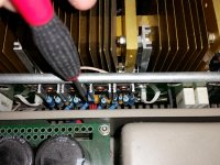
Here is a picture of the location of the pots.
Be careful adjusting, only make a small change in one, measure the DC offset, then try fine tuning the other.
I see test points shown in the schematic, but I could not locate them I the board, so take care in adjusting it too far so it does not run too far out of range.
Attachments
I'm also having a problem with static/cracking in my left channel on my Jungson JA-88D.
I see there are 2 pots per channel for this adjustment as per chillysalsa's attached thumbnail. Am I correct in assuming that these are for fine/coarse adjustment and if so, which is which?
Thanks for any help/advice.
I see there are 2 pots per channel for this adjustment as per chillysalsa's attached thumbnail. Am I correct in assuming that these are for fine/coarse adjustment and if so, which is which?
Thanks for any help/advice.
I do not know this amp but logically, it must be a potentiometer for offset and another for bias.
if we act on the offset, we must adjust the bias, and vice versa.
in any case, both, offset and bias must be controlled.
if we act on the offset, we must adjust the bias, and vice versa.
in any case, both, offset and bias must be controlled.
huggygood...wouldn't logically one pot be for the positive speaker output and the other for the negative speaker output?
Unless it's a bridgemode amplifier, the negative speaker terminal is returned to ground at the power supply. With conventional power amplifiers, there is no possible adjustment to ground potential, just to the differential DC potential which, like the signal, appears at the output+ terminal.
There are nice pictures but unfortunately, there are no technical details at the link to Troel's site and the OP's description is unclear as to what he did. He could just as easily have solved the fault just by resetting a poor quality 15 turn pot. or temporarily "fixing" a soldering fault by pushing a few parts.
There are nice pictures but unfortunately, there are no technical details at the link to Troel's site and the OP's description is unclear as to what he did. He could just as easily have solved the fault just by resetting a poor quality 15 turn pot. or temporarily "fixing" a soldering fault by pushing a few parts.
Hi Ian...it is indeed a bridgemode amp as it runs 4 amplifiers bridged in pairs for the left and right channel respectively.
Well, if bridge mode, all the more reason to get a service manual detailing the offset setting of each amplifier before playing about with them in bridge. If that's not possible, you still need first hand expertise as opinions don't work when no one really knows what the design is like or how best to set it up for correct operation.
I guess the schematics that the OP referred to were taken down from the site as I can't see anything useful there. Perhaps Troels Graveson who is probably also the same person as a member here, can provide contacts and assistance as it seems the design was developed many years ago and well before Jungson assumed production.
I guess the schematics that the OP referred to were taken down from the site as I can't see anything useful there. Perhaps Troels Graveson who is probably also the same person as a member here, can provide contacts and assistance as it seems the design was developed many years ago and well before Jungson assumed production.
Thanks for the reply Ian.
Please excuse my ignorance but I am under the impression that DC Offset should be set as close to zero as possible or am I entirely off the mark here? If there is a specific value I should be shooting for and failing any available Jungson documentation could I just measure the offsets (+/-) of the properly working R channel and replicate this for the L when adjusting?
Please excuse my ignorance but I am under the impression that DC Offset should be set as close to zero as possible or am I entirely off the mark here? If there is a specific value I should be shooting for and failing any available Jungson documentation could I just measure the offsets (+/-) of the properly working R channel and replicate this for the L when adjusting?
my problem is that its losing power. i bought it like that. weak. that means it doesnt go louder after a certain level.
what should be replaced?
what should be replaced?
Hi guys, i know this is a very old thread.
However, i noticed tat there is a thread with same problem on another forum. And there is pictures and instructions how to solve the problem.
Images are hosted on location that might drop the images after some time, so i repost the images here so that it will stay for all ppl to read for a long time.
There is more details in the thread on hififorum.nu, but those comments are written in foreign language.
There is also a diagram for this amplifier (JA-88) and the thread is about the similar model (DA 200 IA) that has less transistors and smaller capacitor bank.
Thread about same issue, will need google translate.
Image shows layout and location of potentiometer, and how to hook up the equipment:
(because there is double amplifier for each channel, the amplifiers has to be checked by hooking up COM to the GND on the PCB at the side of capacitor bank, and the PLUS of the voltage meter has to be hooked up to respecitve speaker termina, MINUS or PLUS dempending on what part of the amplifier one wishs to adjust. The two VR resistors adjust one of the terminals respectivley. Maybe the front adjuster will adjust positive speaker output, and rear adjuster will adjust negative speaker output. When adjusting one of them, both will change)

Image shows how adjusters look like, VR variable resistors:


Image shows state of voltage (mV) before adjustments:

Image shows state of voltage after adjustments made:

The thread also gives a thermal analysis of the amplifier, showing that the problem can somehow be detected using thermal analysis. Indication is that there is a temperature difference that seems to be according to the DC offset problem. And on one side of the amplifier (one channel) the temperatures become even after the DC offset is adjusted. Temperatures vary from 69-77 degrees C.


Diagram, RW3 and RW4 shows the VR resistors:

However, i noticed tat there is a thread with same problem on another forum. And there is pictures and instructions how to solve the problem.
Images are hosted on location that might drop the images after some time, so i repost the images here so that it will stay for all ppl to read for a long time.
There is more details in the thread on hififorum.nu, but those comments are written in foreign language.
There is also a diagram for this amplifier (JA-88) and the thread is about the similar model (DA 200 IA) that has less transistors and smaller capacitor bank.
Thread about same issue, will need google translate.
Image shows layout and location of potentiometer, and how to hook up the equipment:
(because there is double amplifier for each channel, the amplifiers has to be checked by hooking up COM to the GND on the PCB at the side of capacitor bank, and the PLUS of the voltage meter has to be hooked up to respecitve speaker termina, MINUS or PLUS dempending on what part of the amplifier one wishs to adjust. The two VR resistors adjust one of the terminals respectivley. Maybe the front adjuster will adjust positive speaker output, and rear adjuster will adjust negative speaker output. When adjusting one of them, both will change)
Image shows how adjusters look like, VR variable resistors:
Image shows state of voltage (mV) before adjustments:
Image shows state of voltage after adjustments made:
The thread also gives a thermal analysis of the amplifier, showing that the problem can somehow be detected using thermal analysis. Indication is that there is a temperature difference that seems to be according to the DC offset problem. And on one side of the amplifier (one channel) the temperatures become even after the DC offset is adjusted. Temperatures vary from 69-77 degrees C.
Diagram, RW3 and RW4 shows the VR resistors:
Last edited:
What camera/app do you use to take these infrared photos?Temperatures vary from 69-77 degrees C.
Camera used is FLIR lepton module inside CAT S61 camera / phone judging from the pictures.
There is multiple cheap cameras like that from 200 USD and up.
There is multiple cheap cameras like that from 200 USD and up.
Last edited:

I want to add that this is a bridged amplifier.
One of the VR potentiometer is for the positive side of the speaker terminal, and the other VR is for the negative side.
I assumed they should be close to 0mV and the poster adjusted them both that way. Just take care to measure between GND and speaker terminal, not between the terminals, when adjusting.
When both amplifiers for the same channel reach 0mV, then there should be also 0mV between the terminals.
Last edited:
I would not call 200 USD cheap...There is multiple cheap cameras like that from 200 USD and up.
I have the same camera ,Flir Android versionCamera used is FLIR lepton module inside CAT S61 camera / phone judging from the pictures.
There is multiple cheap cameras like that from 200 USD and up.
I have this one https://www.a4.fr/camera-thermique-pro-flir-160x120-pour-smartphone-usb-c.html
but this one is largely sufficient : https://www.fnac.com/Camera-thermique-Flir-One-pour-smartphone/a13703269/w-4
but this one is largely sufficient : https://www.fnac.com/Camera-thermique-Flir-One-pour-smartphone/a13703269/w-4
On Amazon Flir One is 397 EUR:
https://www.amazon.de/-/en/Flir-One-Thermal-Imaging-Camera/dp/B0716ZGL7C/ref=sr_1_1
FLIR TG165-X is 334 EUR:
https://www.amazon.de/-/en/TG165-X-Thermal-Imaging-Camera-Bullseye/dp/B08CRQYQ3R/ref=sr_1_4
If I would need to buy one of these then most probably I would prefer the separate handheld device.
Costly are both of them...
- Home
- Amplifiers
- Solid State
- Jungson JA-88D crackling and static fixed!