Referenced is an output circuit of a Studer A820. My concern is the stuff around Q10, Q15, Q16: isn't that 'simply' a way define the bias for the output stage (Q1, Q2...) for IC2? I will try to sim that for my little problem here.
Rüdiger
Rüdiger
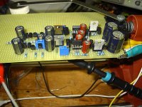
Hello, I present for your consideration what i use for a line driver with great sound quality.
this is a Buffer i use for Headphone Driver Duty however it also functions well as a Line Driver although the THD numbers are not as low as you want and while the circuit likes low impedance loads an output series resistor along with about 100 ohms or real load resistor at the output location works for me. I use a 50k volume pot although a 10k works allot better. Adjustment of the Bias current while under the desired load for lowest THD is also desirable.
this is a Buffer i use for Headphone Driver Duty however it also functions well as a Line Driver although the THD numbers are not as low as you want and while the circuit likes low impedance loads an output series resistor along with about 100 ohms or real load resistor at the output location works for me. I use a 50k volume pot although a 10k works allot better. Adjustment of the Bias current while under the desired load for lowest THD is also desirable.
Attachments
That's a members-only link, would you mind posting it here as an attachment?Onvinyl said:Referenced is an output circuit of a Studer A820....
- Klaus
PMA said:I do not think that 0.0000X% or 0.0000Y% really matters. I am quite sure that stability is an ultimate requirement. For this reason, I tight collectors of an input complementary pair to supply rails, though distortion is a bit higher then, due to Early effect.
Agreed.
A few other points, it looks like the IP pair is running at pretty high
currents, 2mA will be fine and may even lower the distortion.
Also, different devices will have more or less pronounced early effect.
It's worth trying something like a 3423/1360 pair.
Terry
Hi,
thanks, Pavel.
I checked between 6 - 10mA for the IP, I will try to get lower.
Does anyone have spice models for 2sc3423/2sa1360?
Rüdiger
thanks, Pavel.
I checked between 6 - 10mA for the IP, I will try to get lower.
Does anyone have spice models for 2sc3423/2sa1360?
Rüdiger
.MODEL 2SA1360 PNP IS=10F BF=142.067 VAF=100 IKF=89.7634M ISE=72.8872F NE=1.57473 BR=1.28882
+ IKR=10 ISC=113.279P NC=1.60698 RE=1 RC=5.19274 CJE=10P MJE=500M CJC=6.2869P
+ VJC=691.232M MJC=341.918M TF=1.03772N XTF=8.61047M VTF=191.12 ITF=737.477K
+ TR=10N
+ IKR=10 ISC=113.279P NC=1.60698 RE=1 RC=5.19274 CJE=10P MJE=500M CJC=6.2869P
+ VJC=691.232M MJC=341.918M TF=1.03772N XTF=8.61047M VTF=191.12 ITF=737.477K
+ TR=10N
Thanks, do someone have the 3423 as well?
Well, if early effect is a major contributor of distortion in the IP, then FET's should be tried. I didn't manage to get them biased properly with whatever fancy method I tried, though. varying the input resistor changes things widley, sometimes the output is close to one rail, or the output pair isn't on.
It seems best to stay with the topology of post #1. In a another circuit, where this stage follows a fc'ed sym-dif-pair, the net distortion is lower anyway.
FET does not yield Vbe cancellation, as bipolars do. Vbe cancellation (NPN vs. PNP) is a strong point of the diamond buff structure.
Rudiger,
astonishing THD figures indeed, not very faraway from those of commercial amplifiers...
Well again, FETs are true transconductance devices, where the input voltage and the output current is directly related. So for V-I/impedance conversion, using JFETs would be a less troublesome approach, providing superior accuracy and sound quality.
In my eyes, a topology with balanced output is even more fancy.
I can not see why you need two stages for this task.
Hi,
tried some things. I changed values a bit and made a new current source. All the biases in the circuit are strongly interdependent, and additional things might be done, perhaps even a Vbe-multiplier.
Circuit as shown is not stable with 50-R Source impedance (high oscillations that thickens signal forms), but with 500-R it seems working.
the refined circuit:
Attachments

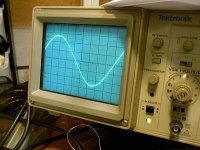
60kHz, 100mV, sine:
Is this blip at the peaks some kind of crossover distortion? It's gone with lower freq's.
Overall, stablity is still a concern. One could provoke some oscillations by arrangement of the suppy leads.
Should you be able to compare the circuit with it's actual build on the photo, comments would be nice.
Lumba, I use at the moment a simple 2-FET follower that sounds real nice. I will compare it when and if the circuit is working. Might learn a thing or two on that way as well...
Rüdiger
Attachments
Hi Rudiger,
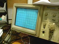
interesting results, indeed. So you have rise time about 150ns now, for small-signal. How is 2MHz square at higher Vp-p? Regarding 60kHz sine distortion at peaks, this is not very good. How about cross-conduction in the output stage? (you might like to monitor voltage across emitter resistors, if you keep it stable after probe connection).
I hope it is not a product of a function generator? (sine peaking).
A two trace display with input and output waveforms would tell you if the amp is generating the blip or if it's in the test signal.Onvinyl said:60kHz, 100mV, sine:
Is this blip at the peaks some kind of crossover distortion? It's gone with lower freq's.
- Status
- Not open for further replies.
- Home
- Amplifiers
- Solid State
- Jung/PMA Line-Buffer