Reposting (sort of) from Tubes/Valves -
Hi all,
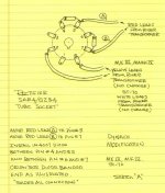
I have a 3-year old JTM45 Metropoulous/Valvestorm kit that had a failure of the rectifier a week ago. It also took out one or both output tubes (KT66's).
This is the second time this has occurred, but the first time the output tubes were OK.
From what I have learned on the other forum:
1. Do not use standby (because of cathode stripping?): Already aware of that, I almost never use standby
2. Excess capacitance causes excess surge current at power up this. I am using the standard Marshall design, 32uF before and after the choke. This might be too much for a modern (sic) 5AR4?
3. This amp for some reason has pretty high B+ of 500VDC but that has not been flagged as an issue.
4. There are better 5AR4's that the Sovteks I have... I have read that there are some good chinese ones...
From the advice I received and reading more I see a few options:
1) reduce the capacitance prior to the choke for 32uF total
2) install resistors (47ohm) between the transformer and plates
3) install thermistor (Amphenol CL-90) either on the primary or secondary side of the transformer or in series with the standby switch
4) Use a different rectifier brand (which I really don't want to do as I have two brand new Sovteks.
Is there any other know solution to this issue? My inclination is to try 1) and 3) on the primary side together.
TIA/Tim
Hi all,
I have a 3-year old JTM45 Metropoulous/Valvestorm kit that had a failure of the rectifier a week ago. It also took out one or both output tubes (KT66's).
This is the second time this has occurred, but the first time the output tubes were OK.
From what I have learned on the other forum:
1. Do not use standby (because of cathode stripping?): Already aware of that, I almost never use standby
2. Excess capacitance causes excess surge current at power up this. I am using the standard Marshall design, 32uF before and after the choke. This might be too much for a modern (sic) 5AR4?
3. This amp for some reason has pretty high B+ of 500VDC but that has not been flagged as an issue.
4. There are better 5AR4's that the Sovteks I have... I have read that there are some good chinese ones...
From the advice I received and reading more I see a few options:
1) reduce the capacitance prior to the choke for 32uF total
2) install resistors (47ohm) between the transformer and plates
3) install thermistor (Amphenol CL-90) either on the primary or secondary side of the transformer or in series with the standby switch
4) Use a different rectifier brand (which I really don't want to do as I have two brand new Sovteks.
Is there any other know solution to this issue? My inclination is to try 1) and 3) on the primary side together.
TIA/Tim
rayma,
- Keep in mind it's 64uF, 32 before the choke and 32 after.... or does the one after the choke not matter?
- I have not seen this diode modification - I'm trying to figure out what it actually does. Isn't it just putting a diode in series with a diode?
- I'll check the voltage rating of the caps - good point!
thx
Post-choke capacitors don't cause the surge current in the rectifier tube, just the first one.
Adding the series 1N4007 diodes increases the tube's reverse breakdown voltage,
and prevents internal arcing.
If your capacitors are rated at under 525VDC, they will have very shortened lifetimes,
especially for the input capacitor. Bear in mind that sometimes the DC voltage will go
even higher, due to the AC line voltage surging.
Last edited:
I'm at a loss to understand what the added diodes do. They are rectifiers in series with the two rectifier sections in the tube. It looks like all the tube does is give a slow warm up. That could be implemented with a resistor-time-delay relay setup more reliably & cheaply.
Adding the series 1N4007 diodes increases the tube's effective reverse breakdown voltage,
and prevents internal arcing. They don't change the controlled warm-up time of the 5AR4,
nor do they reduce the DC voltage drop across the 5AR4 when it is conducting. They only
increase the reverse voltage capability of the circuit. These diodes were not necessary for
5AR4 tubes of 50 years ago like Mullards etc, but they seem to be necessary for many now.
Last edited:
I'll check the voltage ratings of the cap.
As for adding the diodes - it's can't hurt!
What do you think about using a thermistor, about 100 ohms cold, to slow warm up? At least it can't hurt...
As for adding the diodes - it's can't hurt!
What do you think about using a thermistor, about 100 ohms cold, to slow warm up? At least it can't hurt...
See Premier Guitar's Immortal Amp series for a bunch of things that can help protect your amp. Start here The Immortal Amplifier Mod - Premier Guitar
(RobRobinette has a summary here Amp Mods)
(RobRobinette has a summary here Amp Mods)
The 5AR4/GZ34 datasheets allow 60 µF for the 1st filter capacitor.- Keep in mind it's 64uF, 32 before the choke and 32 after.... or does the one after the choke not matter?
Best regards!
Thanks for the help Rayma. I added the diodes. The B+ is actually 450V. It's only 500V when there are no tubes in it. My bad.
I'm at a loss to understand what the added diodes do. They are rectifiers in series with the two rectifier sections in the tube. It looks like all the tube does is give a slow warm up. That could be implemented with a resistor-time-delay relay setup more reliably & cheaply.
If the rectifier fails in such a way that it shorts the AC voltage to the cathode, you have a problem. I believe this may have happened in my case since I lost at least one output tube. With the diode in place, however, that can't happen. I read somewhere that (theoretically) the rectifier can fail and you can keep on playing....
Currently I'm converting a Hammond AO-68 amplifier into a geetaar amp. It also has got a GZ34 rectifier, fed from a 2x380 Vac secondary. As musicians don't want to renounce the standby switch, I also provided it. To prevent the GZ34 from surge overload when standby is thrown on, I added a NTC between cathode and 1st filter cap. It's nominal value is 40 Ohms, but I measured 75 ohms at ambient temperature. Will this be sufficient for the benefit of the - Mullard made - rectifier?
Having the 1st cap continuously connected to the rectifier with the standby switch following isn't an option, as all caps are rated at 450 Vdc, but the idle voltage would rise to 530 Vdc.
Best regards!
Having the 1st cap continuously connected to the rectifier with the standby switch following isn't an option, as all caps are rated at 450 Vdc, but the idle voltage would rise to 530 Vdc.
Best regards!
- Home
- Live Sound
- Instruments and Amps
- JTM45 rectifier failure