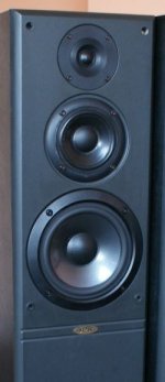
My friend got a pair of old JPW ML 910 speakers. And I would like to help him restore them to original (or close to it) condition. Tweeters are burnt but crossover is another problem. Looks like one coil is missing, one is burnt, one capacitor is not original.
I tried searching internet for crossover schematic but no luck so far. Tried also contacting manufacturer but no reply yet.
Does anyone maybe have schematic or can point me to some direction where can I find it.
New JPW speakers were around $2000 when new in 1992 and would be pitty not to restore them.
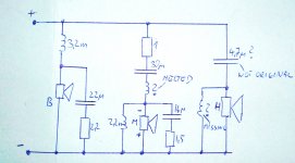
I attached photo of crossover. Both are pretty much the same.
I tried searching internet for crossover schematic but no luck so far. Tried also contacting manufacturer but no reply yet.
Does anyone maybe have schematic or can point me to some direction where can I find it.
New JPW speakers were around $2000 when new in 1992 and would be pitty not to restore them.
I attached photo of crossover. Both are pretty much the same.
Attachments

Nothing too intimidating there, but you must trace the crossover. Looks like the Scanspeak H2606-920000 horn tweeter: Scan-speak H2606/9200 Horn Tweeter
Not expensive. It used to be a Vifa design.
I found a rebuild thread here: JPW ML 910 Speakers Restoration Project | HiFiVision.com
If some bits have gone missing, I think we can reconstruct them. 3 ways tend to follow a pattern. Are the drivers polycones or paper? What size are they?
Not expensive. It used to be a Vifa design.
I found a rebuild thread here: JPW ML 910 Speakers Restoration Project | HiFiVision.com
If some bits have gone missing, I think we can reconstruct them. 3 ways tend to follow a pattern. Are the drivers polycones or paper? What size are they?
Attachments
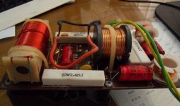
I think drivers are paper. I found that photo of crossover but I would need values of small coils and capacitor.
In that restoration project his crossovers are good, so no details about them mentioned.
Woofer is 165mm and midrange 100mm
In that restoration project his crossovers are good, so no details about them mentioned.
Woofer is 165mm and midrange 100mm
Well, most of the stuff on the interenet is fairly useless because without a crossover diagram we just have another heap of random drivers. 🙄
So you've got to do some work yourself. I need that diagram, then I can fairly quickly work out the missing values. These things are all the same. It helps to measure the DC resistance of the drivers to avoid surprises. Drivers can be tested out of circuit with a 1.5V penlight battery and listening for crackles, or a straight continuity test for resistance.
Trace the earth connection, the live connection and the connection to the drivers, and the components inbetween with as much detail as you can.
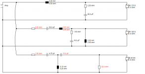
It's got to look a bit like this below. Probably a second order CL tweeter filter at a guess. I modelled a third order. And sensitivity is another factor. Just trust me on this. We'll get there if you do what I say. 🙂
So you've got to do some work yourself. I need that diagram, then I can fairly quickly work out the missing values. These things are all the same. It helps to measure the DC resistance of the drivers to avoid surprises. Drivers can be tested out of circuit with a 1.5V penlight battery and listening for crackles, or a straight continuity test for resistance.
Trace the earth connection, the live connection and the connection to the drivers, and the components inbetween with as much detail as you can.
It's got to look a bit like this below. Probably a second order CL tweeter filter at a guess. I modelled a third order. And sensitivity is another factor. Just trust me on this. We'll get there if you do what I say. 🙂
Attachments
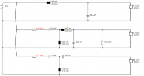
You have done REALLY well in supplying values there, my friend. Here's what I get for a typical 88dB 6 ohm tweeter. The 10uF is optional but lines phase up nicely. The resistors are select on test, but always are a good feature under fault conditions when drivers go open circuit. Protects the amp.
The single 4.7uF idea works with the tweeter in the opposite polarity to the mid, but pushes the tweeters too hard IMO. Party use is the great destroyer of tweeters.
The single 4.7uF idea works with the tweeter in the opposite polarity to the mid, but pushes the tweeters too hard IMO. Party use is the great destroyer of tweeters.
Attachments
Last edited:
I noticed that speakers on your schematics are 8ohms. Does it make much difference if they are 6ohms? I don't know exactly for bass and mid, but original tweeter DC resistance is cca. 3.9ohms.
The missing inductor would explain why your tweeters are burned out! Not many tweeters can stand a 1st order electrical crossover.
I suspect the missing inductor would be around 0.2mH. That would give a 2nd order (electrical) crossover around 3.5kHz.
I suspect the missing inductor would be around 0.2mH. That would give a 2nd order (electrical) crossover around 3.5kHz.
It makes sense regarding missing inductor.
What about melted inductor in series with midrange. That coil is melted on both crossovers. I need to check midrange speakers if they are ok.
What about melted inductor in series with midrange. That coil is melted on both crossovers. I need to check midrange speakers if they are ok.
If you can measure some 3.9R DC resistance in the tweeters, it may just be dried up ferrofluid gone solid stopping them working. This is often replaceable.
As it goes, those coils are possibly still functionally OK:
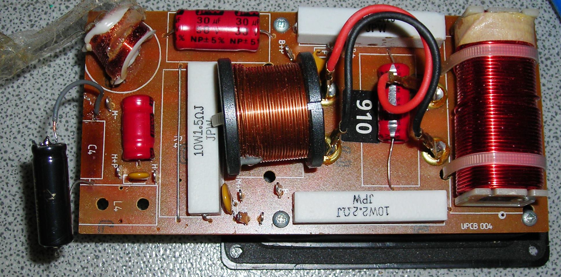
Those little yellow things are polyfuses, which should have protected the drivers. Any coil issues shouldn't have damaged the mids. This looks like a biwireable design that has been shorted out to single ended use.
These things may have overheated through lack of ventilation or being covered in insulating wadding. The plastic moulding may be removable. Maybe a coil with a lower DC resistance through thicker windings will run cooler. It should be aligned away from the big mid coil to avoid crosstalk.
All the drivers I used are 8 ohm nominal but around 6 ohms DC. In fact the G20SC is 4.8R DC. G 20 SC - 8 Ohm | Visaton
The conversion for impedance with a tweeter is something you can almost do in your head. Here root L/C. Root 150uH/4.7uF gives about 6 ohms. With a lower impedance tweeter the cap gets bigger and the coil gets smaller. Impedance is then commendably flat. But I just let Boxsim get on with optimising it.
The corner frequency is, IIRC, 1/2Pi root LC. So you keep the product constant.
Anyway, don't get too prissy with exact values. 10% is near enough usually. If the tweeters are blown, it does look like an 88db type is indicated. Plenty of those about in soft dome and metal and even mylar. You might measure the tweeter faceplate to see what will fit.
As it goes, those coils are possibly still functionally OK:
Those little yellow things are polyfuses, which should have protected the drivers. Any coil issues shouldn't have damaged the mids. This looks like a biwireable design that has been shorted out to single ended use.
These things may have overheated through lack of ventilation or being covered in insulating wadding. The plastic moulding may be removable. Maybe a coil with a lower DC resistance through thicker windings will run cooler. It should be aligned away from the big mid coil to avoid crosstalk.
All the drivers I used are 8 ohm nominal but around 6 ohms DC. In fact the G20SC is 4.8R DC. G 20 SC - 8 Ohm | Visaton
The conversion for impedance with a tweeter is something you can almost do in your head. Here root L/C. Root 150uH/4.7uF gives about 6 ohms. With a lower impedance tweeter the cap gets bigger and the coil gets smaller. Impedance is then commendably flat. But I just let Boxsim get on with optimising it.
The corner frequency is, IIRC, 1/2Pi root LC. So you keep the product constant.
Anyway, don't get too prissy with exact values. 10% is near enough usually. If the tweeters are blown, it does look like an 88db type is indicated. Plenty of those about in soft dome and metal and even mylar. You might measure the tweeter faceplate to see what will fit.
Last edited:
One tweeter still conducts but is physically damaged. Other is burnt and also not original.
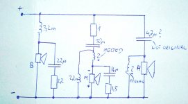
I noticed I did mistake in schematics. Melted inductor is parallel to midrange and 2.2mH is in series. Does this make sense?
I noticed I did mistake in schematics. Melted inductor is parallel to midrange and 2.2mH is in series. Does this make sense?
Nothing too intimidating there, but you must trace the crossover. Looks like the Scanspeak H2606-920000 horn tweeter:
It is not a horn tweeter in this design.
Tweeter mentioned is dome with front horn, not actually horn speaker. But original had JPW part number on it. No idea if they produced it or someone else.
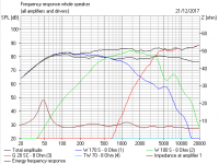
Regardless of the muddle on the mid filter component order, which makes little difference really, we have established certain things. 0.47mH looks good for that burnt mid coil if you need to replace, and I'm not sure you do. We also seem to be looking at a 92dB Vifa D26 104mm tweeter which was a 6 ohm DC design. So the tweeter filter can safely be 3.3uF/0.25mH IMO, maybe adding that 10uF I mentioned for third order, which makes for a brighter sound.
Bit surprising the tweeter doesn't need some attenuation, but that can be added later with a 1 or 2.2R resistor in front. Perheps the polyfuses are taking it down a bit.
Plenty of new tweeters to choose from in 104mm (4 1/4") and 91-92dB. I think you have enough to be getting on with.
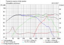
I would take the mid down a dB if that sounds alright to get the impedance up a tidge. It seems to dip low to about 4 ohms around 2kHz. A 2.2R replaces the 1R.
Bit surprising the tweeter doesn't need some attenuation, but that can be added later with a 1 or 2.2R resistor in front. Perheps the polyfuses are taking it down a bit.
Plenty of new tweeters to choose from in 104mm (4 1/4") and 91-92dB. I think you have enough to be getting on with.
I would take the mid down a dB if that sounds alright to get the impedance up a tidge. It seems to dip low to about 4 ohms around 2kHz. A 2.2R replaces the 1R.
Last edited:
- Status
- Not open for further replies.
- Home
- Loudspeakers
- Multi-Way
- JPW ML 910 Crossover