The gate drive is riding on the negative rail though. Negative rail is about -125v. To view the low side form at 5v/div I have to move the reference line up like 115v. I still have outputs out of the circuit. Should I have them in? Could that be why I'm not getting the proper readings?
I should have probably mentioned the no outputs in yet thing earlier. I'm going to put them in. See how it goes.
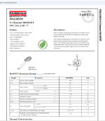
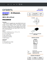
Ok... well... bit embarrassing but got that figured out... I was checking the gate and drain not the source. I had the FDA38N30 datasheet from Alldata for the Fairchild version and according to it, the source was the middle leg... even though, I was pretty sure most all are 3rd leg. Pulled up an OnSemi one and YUP! Been using the wrong pad.
I need to order this amp some new outputs. A few have an RDS of 7-25ohms... while most are 3.5 or less. So, owner said replace them.
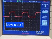
I believe this is what you were looking for Perry? I still had to move the vertical scale up 123v.
I need to order this amp some new outputs. A few have an RDS of 7-25ohms... while most are 3.5 or less. So, owner said replace them.
I believe this is what you were looking for Perry? I still had to move the vertical scale up 123v.
Attachments
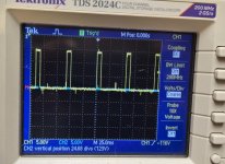
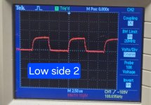
Here is the high side too. Same settings, just vertical scales back to zero. Still no output transistors in circuit.
Attachments
Last edited:
That may work for now but if you can get it right, it will work better. When working as it should, the scope will display a single trace and no matter the DC offset, it will show only the difference in the voltage on the two channels. with 80v of rail and testing the low drive, touching touching either probe (alone) to the gate and drain would send the trace off of the display but when touching both across the gate and drain, the scope would display a 12-15v amplitude waveform at 0v (the reference line).
On the 2184 driver IC (use your multimeter):
DCV across terminals 3 and 5?
DCV across 6 and 8?
What frequency signal are you driving into the amp?
On the 2184 driver IC (use your multimeter):
DCV across terminals 3 and 5?
DCV across 6 and 8?
What frequency signal are you driving into the amp?
Good morning. The only thing I can't seem to find on my new scope is the "Cal" feature. My old one had it. Wonder if that's affecting my readings for differential.
Ok. I'll get those other readings for you shortly. I haven't driven any signal into the amp yet. Will do that today as well.
Ok. I'll get those other readings for you shortly. I haven't driven any signal into the amp yet. Will do that today as well.
Trying to catch up.
With your scope, could you move the 1/2 channels well away (up or down) from the math sweep to get a good view of the differential signal?
With your scope, could you move the 1/2 channels well away (up or down) from the math sweep to get a good view of the differential signal?
Ok. Good day sir. I'm back to this guy.
Pins 3 and 5 have -15.16v and pins 6 and 8 have -8.71v.
If I move the traces away in either direction aside from apart from each other the math trace follows between the lines. I'll try to figure out how to make differential work on this scope.
Pins 3 and 5 have -15.16v and pins 6 and 8 have -8.71v.
If I move the traces away in either direction aside from apart from each other the math trace follows between the lines. I'll try to figure out how to make differential work on this scope.
Ok... I'm just going to put this one aside, till I can get my old scope back to use for this one. I can't figure out how to make the math line a different color. Seems like red is only option and it doesn't seem to want to show what you want to see. I'll just wait. Have other things to get into and feel like I'm wasting your time.
That said, in your tutorial, you mentioned why we don't use differential more... this would be why. LOTS of headaches doing this with newer scopes. This scope is like $3k. I'm sure there is a way... but I can't find it. I'll try again on the weekend, when I have more time for it.
I appreciate your time sir. Thank you.
Last edited:

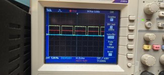
Tektronics tech support for the win!
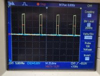
Attached is the differential signal on the low side from both sides. Still red, but the signal nonetheless.
Outputs are in. No signal driven, switches on it's own.
Note: The math is 10v/div. The outputs seem to run nice and cool.
Attached is the differential signal on the low side from both sides. Still red, but the signal nonetheless.
Outputs are in. No signal driven, switches on it's own.
Note: The math is 10v/div. The outputs seem to run nice and cool.
Attachments
That looks good to me.
Differential mode for mains powered scopes makes all the difference when confirming that drive signals are good. It's even better for the high side for amps with all N-channel FETs.
Differential mode for mains powered scopes makes all the difference when confirming that drive signals are good. It's even better for the high side for amps with all N-channel FETs.
- Home
- General Interest
- Car Audio
- JP 43 protection issue