Jolida JD9-I don't understand why an electrolytic cap is between gain resistor & GND
Greetings,
I've been aggressively upgrading my Jolida JD9 phono preamp and don't understand the purpose of C16 (220uf 25V Electrolytic) shown in the attached schematic.

Overall gain of this preamp is selected on another board connected to LJ.
Last night I bypassed C16 altogether and my initial impression was that the JD9 sounded clearer with less distortion during loud complex passages. Of course, time will tell, but I can't imagine why C16 is in a circuit using dual voltage supplies for the OPA's. Can anyone offer an explanation?
If anything, I think a better use for that spot would be to substitute resistors to control the gain of IC3.
Any thoughts about why C16 was put in the design?
Much thanks. Rich
Associated equipment: Grado Statement Sonata1 Low Output (.5mv) Moving Iron cartridge, Sound Valves VTP101 Preamp, Fisher SA300B Power Amp, New Large Advent Speakers.
Greetings,
I've been aggressively upgrading my Jolida JD9 phono preamp and don't understand the purpose of C16 (220uf 25V Electrolytic) shown in the attached schematic.
Overall gain of this preamp is selected on another board connected to LJ.
Last night I bypassed C16 altogether and my initial impression was that the JD9 sounded clearer with less distortion during loud complex passages. Of course, time will tell, but I can't imagine why C16 is in a circuit using dual voltage supplies for the OPA's. Can anyone offer an explanation?
If anything, I think a better use for that spot would be to substitute resistors to control the gain of IC3.
Any thoughts about why C16 was put in the design?
Much thanks. Rich
Associated equipment: Grado Statement Sonata1 Low Output (.5mv) Moving Iron cartridge, Sound Valves VTP101 Preamp, Fisher SA300B Power Amp, New Large Advent Speakers.
If there is a 50mV DC offset going to pin36 of the amplifier. Its gain is set by R9 + R10 / R8 = 100. R11 is for hf roll off. There would be a potential of 5volts DC on the output giving a non symmetrical signal.
Hi,
Pretty poor practise to bypass all the 220uF on the supply
lines with 0.1uF, and not to, a 220uF in the signal path.
Even worse to use a polar electrolytic in that position.
As IC3's input and output is AC coupled, your looking
at a 100 x 10uV output offset, nothing to worry about.
You can bypass that capacitor if you want to, or as
you say fit resistors to reduce the stage gain.
rgds, sreten.
Last edited:
The preceding stage is AC coupled thru C15, so it is the effect of input currents and the huge difference in the current induced voltage offsets if C16 was not there. (The op-amp is a bi-polar input and may have significant input current.)
Unless I am mistaken the R9 + R10 // R11 + C18//C19 sets the pole and zero for the 3180 us + 318us time constants in the RIAA replay curve.
It also appears unless I've totally missed some detail that the input impedance for MM is 100K ohms, which quite well removed from the standard. I am not sure what sort of effect this might have on the cartridge HF performance.
Good eye.It also appears unless I've totally missed some detail that the input impedance for MM is 100K ohms, which quite well removed from the standard. I am not sure what sort of effect this might have on the cartridge HF performance.
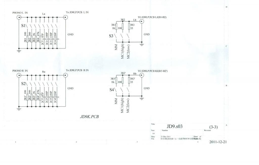
There is a separate board (JD.S03) shown in the original post that sets the capacitance and load. It is connected to the solid state section via ICZ2.
I removed R1 and jumpered over C2, the load and capacitance are now set by the separate board (JD9.S03).
I also changed the 7815/7915 regulators to 7812/7912 because I thought IC3 was glaring a bit. Plenty enough gain with +/-12VDC for a 0.5mv MI cartridge.
For a dual supply amp, the capacitor made no sense to me, bypassed or not.Pretty poor practise to bypass all the 220uF on the supply
lines with 0.1uF, and not to, a 220uF in the signal path.
Even worse to use a polar electrolytic in that position.
I'm new to opamps, so I can't say I fully understand that statement. I have successfully used OPA637 in that position before I made any changes, and OPA637 is said to be unstable at unity gain.That cap forces unity gain at DC so that the op-amp does not amplify its input offset.
So Wow! Now I'm really confused. I'm more used to tubes, not so much with the solid state stuff. I need to read more.
But...the preamp has never sounded better, which is a good thing.
Thanks guys.
For a dual supply amp, the capacitor made no sense to me, bypassed or not.
I'm new to opamps, so I can't say I fully understand that statement. I have successfully used OPA637 in that position before I made any changes, and OPA637 is said to be unstable at unity gain.
The second op amp needs to have a resistor to ground from the inverting input of 250 Ohms or less (gain of 5 or more),
because the OP-37 requires a minimum high frequency gain of 5 to be stable. There appears to be a socket for that part.
The capacitor to ground in the RIAA feedback loop reduces the output DC offset of that stage by making the low frequency gain +1, something different.
The high frequency gain there is 1+100/11 (10.09), which is ok for the OP-37.
Last edited:
C16 could be the rumble filter.
This amp is for turntables, isn't it?
220uF / 200R is 3dB @ 3.6Hz
This amp is for turntables, isn't it?
220uF / 200R is 3dB @ 3.6Hz
C16 could be the rumble filter.
This amp is for turntables, isn't it?
220uF / 200R is 3dB @ 3.6Hz
It could have been tuned that way, to serve two purposes at once.
C16 could be the rumble filter.
This amp is for turntables, isn't it?
220uF / 200R is 3dB @ 3.6Hz
Isn't that a bit low for a rumble filter?
jeff
Not really, that's a filter to remove the really nasty woofer pumping caused by mechanical resonances in the turntable.
Isn't that a bit low for a rumble filter?
jeff
33 rpm is .555 Hz
IMHO a good choice since 220uF is a standard value.
🙂
I cannot begin to guess or offer a technical explanation as to why C16 was in the design, or what effect it's removal has had. But I will say that along with other factors inherent with my system, the Jolida JD9 phono stage sounds better without C16 in circuit. Perhaps it was included as some sort of safety to make the JD9 a "Jack of all trades" phono stage.
The JD9 sounds much better without C16. And I do not make this statement lightly. I spent the better part of the afternoon listening to classical, orchestral, vocal and rock music, and the JD9 now sounds tonally "normal". The gain is there, as is the transparency, attack, and balance. I can honestly say that I am done "tweaking" my JD9 phono preamp because I cannot find any deficiency in it's performance.
This sucker is really clear and uncolored. The truest sounding phono stage I have heard to date using a Grado Statement Sonata1 cartridge. Bells ring like bells, real piano's sound like real pianos, toy pianos sound like toy pianos, and strings have depth, body and individuality. These are the things I was looking for, tonal accuracy. I can finally put the screws back in the cabinet and move on to other things.
Thanks for your input. The rumble filter comments pointed me in the right direction.
Not too surprised to hear this, the quality of that electrolytic would have to be superlative not to have any audible or measurable effect on the performance particular as it is a polar type with no significant DC across it. ESR and ESL are frequency dependent so there could also be a small, but measurable effect on flatness of frequency response, and there are some distortion mechanisms as well in large value electrolytics that seem to come into play with very low DC offsets and low signal amplitudes - suffice it to say I have been very unpleasantly surprised more than once by this.
As long as the offset at the output of the op-amp is not excessive I would not expect its omission to cause particular problems.
As long as the offset at the output of the op-amp is not excessive I would not expect its omission to cause particular problems.
Not too surprised to hear this, the quality of that electrolytic would have to be superlative not to have any audible or measurable effect on the performance particular as it is a polar type with no significant DC across it. ESR and ESL are frequency dependent so there could also be a small, but measurable effect on flatness of frequency response, and there are some distortion mechanisms as well in large value electrolytics that seem to come into play with very low DC offsets and low signal amplitudes - suffice it to say I have been very unpleasantly surprised more than once by this.
This capacitor is "standard equipment" in many power amplifiers, imagine what it does to their sound.
J Curl has long insisted on a servo for his amplifiers, instead of this quick and dirty circuit.
I've been looking for a new preamp since I got the LOMI Statement Sonata1. Had I realized clean gain would be such a problem, I would have purchased a LOMC and used a Step Up Transformer. I even tried a head amp, too much hiss.
I've looked at dozens of schematics for phono stages and the JD9 was the only one using a dual supply AND that capacitor. It's advertised as being very flexible, able to handle any cartridge and very easy to upgrade. Perhaps C16 was put there to make this "jack of all trades" preamp more stable.
Jolida has recently come out with an updated model. I wonder what the schematic looks like.
- Status
- Not open for further replies.
- Home
- Source & Line
- Analogue Source
- Jolida JD9-I don't understand why an electrolytic cap is between gain resistor & GND