PaulyT said:Another small issue with the schematic, which shows C2 oriented with negative to ground; but since this is F- it should be positive to ground, right? Which is how it is on the PCB...
Yes, C2 is backwards in the schematic. The silk screen is correct, so just be sure to follow that. The only silk screen error I am aware of is the output tube pin-outs. They are rotated 180 degrees. The schematic also doesn't show the grid stoppers (R31,R32), but they are there on the PCB.
Yeah, not sure about the switch in the back, but it's one less thing for kids to have access to, and fewer panel components for me to mount... I'll have it in the back for now.
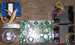
Here's my completed board, with caps and the two jumpers for 5V/300B operation. Cleaned and ready to connect to various external bits.
What do you guys do for temporary connections during the checkout? Do you just solder lightly, or use alligator clips, or...?
Here's my completed board, with caps and the two jumpers for 5V/300B operation. Cleaned and ready to connect to various external bits.
What do you guys do for temporary connections during the checkout? Do you just solder lightly, or use alligator clips, or...?
An externally hosted image should be here but it was not working when we last tested it.
Thanks!
I think I've found my enclosure:
Hammond perforated cover (17x10x5.2, black)
Hammond steel chassis (17x10x3, black)

It should give me a little over 8 inches internal clearance, enough for the tubes and all. The 3" on the bottom box gives adequate space for all the panel connectors.
I can also get handles. And the steel frame should be strong enough to carry the full amp by the handles, right? I would worry about this with aluminum... but the black steel chassis matches the cover, anyway, and is only a few dollars more.
Is it a lot harder to drill/cut holes in the steel, compared to aluminum? That's the only part I worry about, as I don't really have tools for this... Recommendations? I guess I can use a simple drill for most of it, except for the power cord socket which will need a larger rectangle. I have a good jigsaw, will I be able to cut the steel chassis with a decent metal blate?
How do you usually mount the transformers? They need to be raised up a bit since the wires all come out the bottom. I guess I can put them on wood blocks...
I think I've found my enclosure:
Hammond perforated cover (17x10x5.2, black)
Hammond steel chassis (17x10x3, black)
It should give me a little over 8 inches internal clearance, enough for the tubes and all. The 3" on the bottom box gives adequate space for all the panel connectors.
I can also get handles. And the steel frame should be strong enough to carry the full amp by the handles, right? I would worry about this with aluminum... but the black steel chassis matches the cover, anyway, and is only a few dollars more.
Is it a lot harder to drill/cut holes in the steel, compared to aluminum? That's the only part I worry about, as I don't really have tools for this... Recommendations? I guess I can use a simple drill for most of it, except for the power cord socket which will need a larger rectangle. I have a good jigsaw, will I be able to cut the steel chassis with a decent metal blate?
How do you usually mount the transformers? They need to be raised up a bit since the wires all come out the bottom. I guess I can put them on wood blocks...
PaulyT said:Is it a lot harder to drill/cut holes in the steel, compared to aluminum? That's the only part I worry about, as I don't really have tools for this... Recommendations? I guess I can use a simple drill for most of it, except for the power cord socket which will need a larger rectangle. I have a good jigsaw, will I be able to cut the steel chassis with a decent metal blate?
Steel is more difficult to work, yes. They do make metal cutting blades for jig saws. What I've done on steel computer chassis is to scribe the square hole, drill medium sized holes around the perimeter, cut-out the center, and then straighten everything with a nibbler tool or a file.
Those expensive Greenlee punches can also punch through steel up to a certain gauge. I use mine more often for punching through electrical boxes than for tube amps. They should work fine on that chassis. Another thing you can use are step-drills...those cone-shaped things. They work pretty well if lubricated properly.
PaulyT said:How do you usually mount the transformers? They need to be raised up a bit since the wires all come out the bottom. I guess I can put them on wood blocks...
There is no need to raise them. Typically, you would drill holes directly under the bells where the wires come out. Use large rubber grommets to protect the wires.
Thanks. Yes, Greenlee are a bit overkill for a single amp... I think it's time for me to at least get a decent drill press.
As for the transformers, and the motor run cap: I don't have an internal frame to mount these on, hence my need to step them up a bit. I think what I'll do is have a wood block under them, drill out holes/channels to route the wires, and bolt the entire thing to the bottom of the chassis. It's either that or cut holes in the bells themselves, which I'd rather not try to do.
When mounting the two OPTs, is it better to have them facing the same way, or have one rotated 90 degrees w.r.t. the other?
It should be but make sure to put large diameter metal washer inside of screw mount so that the screw doesn't rip through the hole. I've made a tube amp with that chassis size which had PT, OPT, choke, motor run caps and all, it weighed about 60 lbs. Watch your back when you lift it. A weight belt may help.PaulyT said:I can also get handles. And the steel frame should be strong enough to carry the full amp by the handles, right?
")
I use Greenlee step bit for smaller holes. Ebay has them cheap. It cuts cleaner than drill bits. You just have to be careful not to go past the right hole size. I put a piece of masking tape to see where to stop. For larger holes (> 3/4"), I use their hole punch but I find hole saw also effective.Is it a lot harder to drill/cut holes in the steel, compared to aluminum? That's the only part I worry about, as I don't really have tools for this... Recommendations? I guess I can use a simple drill for most of it, except for the power cord socket which will need a larger rectangle. I have a good jigsaw, will I be able to cut the steel chassis with a decent metal blate?
If they are under 5 inches tall, you can mount them on top of bottom chassis. The cage will still fit.How do you usually mount the transformers? They need to be raised up a bit since the wires all come out the bottom. I guess I can put them on wood blocks...
So if I read this right, you are planning to have everything sit inside the enclosure - with no top plate correct?
You shouldn't have a problem mounting the OPT's this way, but the power xfmr has too many wires for that to work. You could just take the bells off...
Have you laid this all out to see if it will fit yet? With those big OPTs you might not have enough space.
I have the same chassis size that you pictured here, except that mine is aluminum. I also bought the top plate so that I could mount my xfmrs and it gave me a little extra room inside.
PaulyT said:As for the transformers, and the motor run cap: I don't have an internal frame to mount these on, hence my need to step them up a bit. I think what I'll do is have a wood block under them, drill out holes/channels to route the wires, and bolt the entire thing to the bottom of the chassis. It's either that or cut holes in the bells themselves, which I'd rather not try to do.
Oh, you are mounting the transformers under the chassis? The power transformer is that short? Hammond transformers have punch-outs in the bells to let you do this. Some bells have enough clearance to get the wires out from under the bell (the UBT-2s) while others don't. I know the Edcors are tight.
PaulyT said:When mounting the two OPTs, is it better to have them facing the same way, or have one rotated 90 degrees w.r.t. the other?
The OPTs should be rotated 90^ wrt the power transformer and on the sam e center line if they are close together. If they are far apart, it's not very important. The idea is to prevent flux from the power transformer core from inducing flux currents in the OPTs. The OPTs can bee parallel...I've never seen anyone worry about that.
Since you are using a steel chassis, grounding will be more important since the power transformer will induce currents in the chassis. Make sure you only ground to the chassis at a single point and try to keep the power transformer and choke away from everything else.
Correct, the plan is to not use the regular chassis cover, since I'd just have to cut out so much of it anyway. Yes, I've measured a general layout with the PCB + tubes in the center, PT + choke + motor run cap on the left, OPTs on the right. Should fit everything ok, with room in the back center of the chassis for the connectors. (The front/back edges are the 17", so it's wider than it is deep.)
I will mount the PCB with usual spacers/washers. For everything else, what I'm imagining is 3/4" MDF or something, as strips on the left and right sides. I will cut channels so the wires will go out the bottom of the transformers, through the channels, and out to the PCB/connectors. I can make the channels as wide as necessary to fit all the wires. The mounting bolts for the transformers will just go through the wood and bottom of the chassis, so that everything will be secured together.
I will mount the PCB with usual spacers/washers. For everything else, what I'm imagining is 3/4" MDF or something, as strips on the left and right sides. I will cut channels so the wires will go out the bottom of the transformers, through the channels, and out to the PCB/connectors. I can make the channels as wide as necessary to fit all the wires. The mounting bolts for the transformers will just go through the wood and bottom of the chassis, so that everything will be secured together.
Here's the layout I'm thinking about. This should fit within the 17x10 space (actually a little less because of the lip of the chassis top). I would like to have the board facing this way so you can see the tubes more, but could rotate it if necessary.
I'm not sure how far away you mean for the choke and PT...? I'm also trying to minimize the wire lengths to these external parts, though maybe that's not a big dea. But that's why I put the choke and run cap near that corner of the board.
I'm not sure how far away you mean for the choke and PT...? I'm also trying to minimize the wire lengths to these external parts, though maybe that's not a big dea. But that's why I put the choke and run cap near that corner of the board.
Attachments
OK, I understand your approach now. Yeah, that arrangement will be fine. You could mount the transformers even higher to further minimize any induced currents, but 3/4" is pretty good.
The tubes will light up the interior, so you will probably be able to see the PCB pretty well. 300Bs aren't terribly bright...the brightest tube will probably be the 5AR4. So I imagine you won't see a whole lot through the cage. You could always make a couple of aluminum plates to cover the side areas and hide the wires and transformers a bit, if it bothers you.
The tubes will light up the interior, so you will probably be able to see the PCB pretty well. 300Bs aren't terribly bright...the brightest tube will probably be the 5AR4. So I imagine you won't see a whole lot through the cage. You could always make a couple of aluminum plates to cover the side areas and hide the wires and transformers a bit, if it bothers you.
PaulyT, you could try this.
Have a bottom plate so that you can access the board easily and on top, the cut out around the TSE board area with a separate cover (preferably aluminum) can also make it easy to put multimeter probes. Then install the cage on top of all this.
An externally hosted image should be here but it was not working when we last tested it.
Have a bottom plate so that you can access the board easily and on top, the cut out around the TSE board area with a separate cover (preferably aluminum) can also make it easy to put multimeter probes. Then install the cage on top of all this.
Interesting idea, thanks! That could certainly work, too. Would mean a little more cutting and fitting, esp. for the tube cover... plus I have that Triad choke which is ugly, not sure it'd fit in the bottom part. Or if you mean the cage on top of everything, cap and transformers and all, well I'm not sure the big motor run cap I have will fit under just the cage part, at least not standing straight up.
I'll stick with my relatively simple plan for now, but I appreciate the feedback from you all! I'm ok with having a single big box that encloses everything, I know it's not the traditional tube amp style. Aesthetics in DIY projects has never been my strong suit!
I'll stick with my relatively simple plan for now, but I appreciate the feedback from you all! I'm ok with having a single big box that encloses everything, I know it's not the traditional tube amp style.
Aesthetics in DIY projects has never been my strong suit!So, as far as hooking up the power transformer: I assume, for 300B, that I'm using the 660V taps in the Edcor XPWR131, going to T1-4 and T1-5 on the PCB, with the center tap going to T1-1. Right?
However, which of the 6.3V and 5V taps go to which inputs on the board - T1-2,3 and T1-7,8 (T1-6 is not used)?
Edit: ah, from indirect clues in the manual, looks like T1-2,3 is 5V, and T1-7,8 is 6.3V?
However, which of the 6.3V and 5V taps go to which inputs on the board - T1-2,3 and T1-7,8 (T1-6 is not used)?
Edit: ah, from indirect clues in the manual, looks like T1-2,3 is 5V, and T1-7,8 is 6.3V?
- Status
- This old topic is closed. If you want to reopen this topic, contact a moderator using the "Report Post" button.
- Home
- More Vendors...
- Tubelab
- Joining the Tubelab SE club