

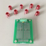
Heat shrink worked like a charm. I cut off 15 mm, and made two holes for the legs to stick out. Applied the heat gun with the coil and heat shrink on the forming tool. Then wait for it all to cool down. The coil is hard now like it's held together with adhesive. Much easier to handle without damage. Clear makes it easy to see the coils are still nicely formed and no gaps.
Attachments

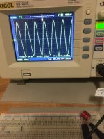
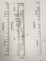
The coil works! The BK Precision Function Generator lead arrived today. I setup the test following John's coil video. Selected a 1K resistor and a 1nF (102) ceramic capacitor that measured 780 pF. Found the peak by adjusting the frequency dials on the Function Generator. The peak was at 5.26 MHz. Using the Radio Shark chart drew a line from 5.3 MHz, through 800 pF to 1.1 uH.
Attachments
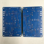
Most of the components are soldered in. Only ones left are the bias trim pot and the output transistors.
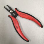
I used these clippers to trim all the leads to the same length on the back of the PCB. See YouTube video from Mr SolderFix called "PTH /Through Hole Soldering , Made Easy - Beginners Tutorial" for his technique and use of a similar trimmer.
I used these clippers to trim all the leads to the same length on the back of the PCB. See YouTube video from Mr SolderFix called "PTH /Through Hole Soldering , Made Easy - Beginners Tutorial" for his technique and use of a similar trimmer.
Attachments

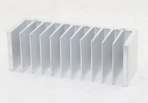
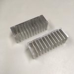
I ordered some heat sinks 130 x 45 x 45. I'll wait for them to arrive. It will be a couple of weeks before I make any further progress.
Until then how about some more coil humour? Coil Team 6 have infiltrated the Super Villain's evil lair to rescue one of their own.
Until then how about some more coil humour? Coil Team 6 have infiltrated the Super Villain's evil lair to rescue one of their own.
Attachments

Can we see the wounded coil 6 member being carried to safety or the Super Villain get some rough justice? 😀
Hope the coils gets inducted on the board in full capacity and this nice project winds up in success.Until then how about some more coil humour? Coil Team 6 have infiltrated the Super Villain's evil lair to rescue one of their own.
sorry couldn't resist 🤦♂️
🤣 🤣 🤣In the end, the abducted coil was "sprung" from captivity. No coils were harmed in the making of this picture.
Heatsinks arrived. Fast than expected. Excellent packaging. They each came with 8 holes drilled and tapped for 3mm screws. The holes almost line up with the PCB. I'll drill and tap another hole in the center. I'll also use some fine grit sandpaper attached to some MDF to flatten the face and polish out any raised dings and mill marks.
Attachments
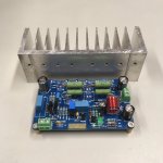

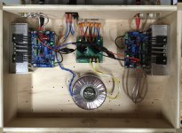
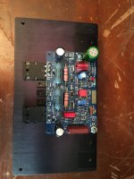
JAT501 works! The parts came together installed into a plywood test box. Passed smoke test using a small 12-0-12 transformer and 3A inline fuses. No pops or shorts. Then swapped out the 12V transformer for the 17-0-17 toroidal transformer as shown.
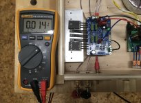
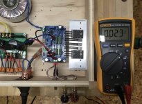
See photos for initial tests results. DC offset on the speaker terminals measured 14 mV left and 23 mV right. Left and right bias set to 26 mV measured across the emitter resistors following John's design document.
Connected a preamp and speakers and played some music for about an hour. Sounds great. No hum or obvious distortion. The output transistors got warm to the touch, but not hot.
Attachments


Amp looks like a "P3A" , but with current source(s). Green LED works good , red led + 330R (R4) is more thermally stable.
Also , with 100pF ... it is over compensated (a good thing). LTP Re could be reduced to 68-100R , less THD in audio band.
Most modern output transistors ,show (and simulate) lowest THD at 50-70mA (11-15mV across the .22's). 15mV with single
output pairs. For subs - or 2 pair outputs , I run as low as 6-7mV - can't hear X-over garbage over a sub , runs cooler.
Nice compact super reliable circuit. All 20'th century Behringer powered speakers use this same circuit.
OS
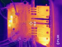
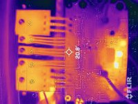
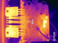
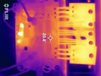
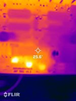
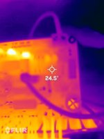
I took photos of the boards with my FLIR camera. Listening at a "reasonable volume". Q7 and Q9 are relatively warm compared to the rest of the board. Also some heat at the Q2 to Q5 cluster. The output transistors are warm as expected. Looks good to me.
Attachments
Last edited:
I want to see what the whole machine looks like
Englidh please
dave

diyAudio moderation team
- Home
- Amplifiers
- Solid State
- JohnAudioTech JAT501 Build Thread