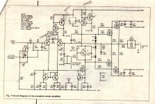
A BJT version!
There is an illegible indication of bias current setting at points 6,14 where Red and Blue are written. Is this 83 mA? R16 is intended to set the bias current in the output stage, which will be less that the current shown. A class B design can even be adapted to use as a class A amplifier and the bias current setting increased to that required to prevent each output transistor from switching off when not conducting as the output voltage swings from +ve to -ve peaks.
However, this translates to considerable (amps) bias current passing through the output devices which is wasted entirely as heat and large heatsinking indeed would be required to cool 2 amplifiers supplied with ~37V rails and still drive 4R speakers, as this one is. Think of a 4U rack case with 3 sides covered in deep finned heatsinks, or fan forced cooling to dissipate around 400W, if this design were operated in full class A.
I can't see anything of that size fitted to your amp and seriously, the sink fitted to the rear panel is not really sufficient for a single channel even in class AB at half power. I guess you never tested this or played it very loud. For most users interested in amplifiers like this, it probably won't make any difference whether it delivers 8W or 80W as they will probably never need that amount of power.
We often see references to various sections of amplifiers running in class A. Virtually all other parts of amplifiers actually operate in class A, as the currents involved are miniscule so the power loss is negligible and the results optimal. The output stage is seldom so, as explained. If amplifiers are class A, they will generally operate with lower voltages and power output than conventional types of similar proportion in order to keep heat and costs to a minimum.
For examples of even low power class A amps with barely enough cooling, have a look at Musical Fidelity's earlier products line up. Sugden produced them as a staple.
Last edited:
I'm not sure about this one but the later Mos-Fet 80W JLH amplifier was definitely not Class A. It used similar sized heatsinks and barely gets warm.
ian, i followed jlh's recommendation , off memory and notes i think quiescent current was set to be stable around 75-80ma once up to temperature.
i guess the aluminium L bracket , heatsinks and the heavy weight of the back plate helped keep it cool. It weighs in at about 13 kg ( helped by a massive torroidal )
i guess the aluminium L bracket , heatsinks and the heavy weight of the back plate helped keep it cool. It weighs in at about 13 kg ( helped by a massive torroidal )
Well, there you go, you've answered the Class A question. Biassed at 80mA it is only Class A at and around the crossover region, thereafter it is Class B.
160 viewings for this in 2 days !! , have i set the price correctly at £75 starting bid.
i thought this might be hardly looked at being a bit esoteric
i thought this might be hardly looked at being a bit esoteric
I'd have thought that £75 was a bit high for a DIY project. But you never know who might be looking.
I was interested in it @ some little way over £75, that would bring the total cost to ~£100 for 3 channels of Lateral mosFET JLH.
But is it not 3channels of JLH and it is not lateral, not even mosFET.
I am glad I asked for details.
Take me off the watching list.
BTW,
80mA of output bias equates to ~0.1W of ClassA output (0.16mApk)
But is it not 3channels of JLH and it is not lateral, not even mosFET.
I am glad I asked for details.
Take me off the watching list.
BTW,
80mA of output bias equates to ~0.1W of ClassA output (0.16mApk)
AndrewT, you can take yourself off the watch list, just go to the items you are watching and delete anything you no longer wish to watch. There's a check mark box for each item and a global delete.
andrew, i am not understanding you
this is 3 seperate amps designed by jlh. each fed by its own supply and smothing capacitors.
or is it that you wanted 6 amps 2xtreble, 2xmid, 2x bass
i rationalised that very little work is done by tweeter but most difficulty is presented by the mid and bass thereby putting them on separate amps
are you not interested or is the price a little high
This was a specific JLH Mosfet amplifier thread. It's also probably not wise to advertise our auctions here anyway. That's for the swapmeet or vendors forums, even if it's very interesting to members with like interests.
You could have anticipated someone would point out the differences bluntly, when what they were looking for turned out be something quite different. i.e it aint a JLH 80W Mosfet Amplifier. I think he's just making some points, really.
You could have anticipated someone would point out the differences bluntly, when what they were looking for turned out be something quite different. i.e it aint a JLH 80W Mosfet Amplifier. I think he's just making some points, really.
Last edited:
CeeBee that particular amp is not the Lateral MOS-FET JLH. It is the inferior BJT version. It uses the 2N3773s as opposed to the Hitachi 2SKxx 2SJxx pair for the lateral MOS-FET design.
Attachments
Last edited:
apologies , thread title was 80watt amp - no mention of mosfet.
my amp IS jlh design !!
what is BJT
my amp IS jlh design !!
what is BJT
Hi cee1bee
Do you still have details of the mods you made to the JLH circuit? I am trying to rebuild it at present, and am having trpuble locating many transistors. My kit came from Radio spares & TV in Johannesbut which I built in 1975, repaired in 200, and need to repair again. This kit already used different transistors. Details avail if you want
Joy
Hi Joyful and welcome to DIYaudio
Did you see and recognize the schematic in post #20? There is so much confusion from the age of this project, it seems no one remembers what they actually built. AFAIK, in the 1970s there were no Mosfet amplifier kits anywhere and JLH was well known for his very popular 75W transistor amplifier published in HFN&RR as a DIY project. That schematic, with suitable substitute components (some are already marked on it) should build and work as originally published. Your substitute components could well be different again but that may not be critical in some locations.
I have seen the circuit republished as a hand drawing in one of JLH's own books - Audio Electronics, I think, around 1991 so I don't think, given magazine copyright issues, that he modified it other than assisting with parts substitutions. If others "borrowed" the design for their own commercial purposes, it's anyone's guess what the design's identity then became.
I see you have already posted in another thread where John Ellis also posted the only mod. circuit suggestions I'm aware of from recent years at posts #91,92,93: http://www.diyaudio.com/forums/soli...coupled-high-quality-stereo-amplifier-10.html
John's mods that were already proven, were checked out also by DestroyerX, and detailed in #19. Have you had a close look at that?
http://www.diyaudio.com/forums/soli...-coupled-high-quality-stereo-amplifier-2.html
- Status
- Not open for further replies.
- Home
- Amplifiers
- Solid State
- John Lindsley Hood 80 watt mono