Wavebourn said:Syn08, what is ground loop inside of the console? Ground in console is an extremely tricky thing, because of multiple ins/outs and inserts.
Don't know about consoles, but having multiple grounding points inside the metal box transforms the case into a giant loop, waiting to capture magnetic fields. Each variable magnetic field line touching the metal walls will induce a voltage in the ground circuit. A horror scenario.
syn08 said:
Don't know about consoles, but having multiple grounding points inside the metal box transforms the case into a giant loop, waiting to capture magnetic fields. Each variable magnetic field line touching the metal walls will induce a voltage in the ground circuit. A horror scenario.
That's why design of consoles is kind of art.
dimitri said:
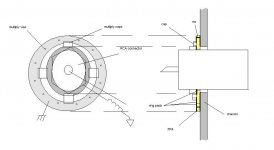
Make a washer like this
What are the "vias"?? What do they do?
What value caps are proposed?
What value inductor to ground?
What of the resonance of the two?
Let's see if this is actually expensive or practical...?
_-_-bear
The Neutrik EMI-XLR has exactly the same construction, so you may want to peek how they sized the components ...😉
Jan Didden
Jan Didden
Attachments
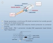
janneman said:The Neutrik has a bead on the pin 1 lead that is 24ohms at 1MHz, and the annular caps filter has an Fc of 10Mhz.
Jan Didden
URGH! A single panel model, $26/pc and 117 days lead time 🙁
http://canada.newark.com/neutrik/nc3fdx-emc-spec/panel-mount-connector-3-pin-female/dp/20M0465
Anyways, they are all for balanced connections. Anything similar for single ended?
syn08 said:
Anyways, they are all for balanced connections. Anything similar for single ended?
😀
Attachments
syn08 said:
Don't know about consoles, but having multiple grounding points inside the metal box transforms the case into a giant loop, waiting to capture magnetic fields. Each variable magnetic field line touching the metal walls will induce a voltage in the ground circuit. A horror scenario.
What about the following scheme in unbalanced connection
Have ferrite chokes in any connection between case/protective earth and signal ground with back to back diodes in serie for LF ground loops.
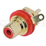
For I/O's, use RCA connectors ( if necessary) with connector case isolated from equipment case and use shielded twisted pair with shield directly connected to equipment case, better use XLR connector
JPV
Sorry, I am slow on the up take... still don't know what the "via" is or does, or where it is in side view from dimitri...
Edit: sorrrryyyy... now I see it, the hard way to get around the corner to make the ground connection on the other side of the "ring/washer". ah ha.
A drill, a hole saw and a trip on a lathe, and one could knock these out pretty fast... but as Anatoly suggests there are other ways of getting those caps in place... 😉
So, is there agreement on this idea/method?
But what about single ended connections, where the shield is also the return?? Must we now go with another triax connector ("new RCA"?) with a signal return wire and an RF outer shield? And what of the added capacitance?
_-_-bear
JPV said:
For I/O's, use RCA connectors ( if necessary) with connector case isolated from equipment case and use shielded twisted pair with shield directly connected to equipment case, better use XLR connector
Still ground loops, and were are trying to avoid the magnetic fields which are not stopped by the wire shielding. Short of a single point of connection between the ground and the case or a massive silver case 🙂 I don't think there is any other optimal solution.
Grounding each I/O to the case works fine for RF because the EM field will not penetrate the case, and the currents will stay on the external side (aka "skin effect").
RF grounding as Dmitri described would work perfectly fine, but I don't see this as a practical option (unless there's a manufacturer out there ready to ship a full range of such connectors at a reasonable price). And then again, how many amps are intended and designed to work in a RFI rich environment?
syn08 said:
And then again, how many amps are intended and designed to work in a RFI rich environment?
All of them, unfortunately. I ask to switch off cellphones before concerts begin.
but I don't see this as a practical option
take RCA connector with nylon washers and replace one of them with the round PCB
Attachments
Wavebourn said:
All of them, unfortunately. I ask to switch off cellphones before concerts begin.
You are a professional, I am just an amateur. Set aside I don't need to close my BB or remove the cordless phones when enjoying vinyl, I don't design for business(es) anyway.
I maintain that for 90% of DIYers, the RFI impact on the audio chain is minimal and can be safely neglected. Just take care of those ground loops.
dimitri said:
take RCA connector with nylon washers and replace one of them with the round PCB
No thank you 🙂 To much work and money for an elusive positive impact.
syn08 said:
Still ground loops, and were are trying to avoid the magnetic fields which are not stopped by the wire shielding. Short of a single point of connection between the ground and the case or a massive silver case 🙂 I don't think there is any other optimal solution.
Grounding each I/O to the case works fine for RF because the EM field will not penetrate the case, and the currents will stay on the external side (aka "skin effect").
RF grounding as Dmitri described would work perfectly fine, but I don't see this as a practical option (unless there's a manufacturer out there ready to ship a full range of such connectors at a reasonable price). And then again, how many amps are intended and designed to work in a RFI rich environment?
The electromagnetic far field will be picked up by the shield.
The magnetic field from any near field wire will see three loops:
1 the twisted pair signal loop ( wire and return) from equipment one to equipment two, there we have good magnetic immunity because of twist.
2 the loop made of the signal return wire ( cold wire of twisted pair), the two signal grounds, the diodes and chokes in series and the protective earth ( green wire). This critical loop has high impedance at RF because of chokes and is broken at LF because of diodes.
3 the loop made of equipment case , twisted pair shield and protective earth. This one will see large noise currents but outside signal path and coupling to loop 2 will be low because of high impedance of loop 2
A very good shield with low cutoff frequency will be effective
What do you think?
JPV
JPV said:
The electromagnetic far field will be picked up by the shield.
The magnetic field from any near field wire will see three loops:
1 the twisted pair signal loop ( wire and return) from equipment one to equipment two, there we have good magnetic immunity because of twist.
2 the loop made of the signal return wire ( cold wire of twisted pair), the two signal grounds, the diodes and chokes in series and the protective earth ( green wire). This critical loop has high impedance at RF because of chokes and is broken at LF because of diodes.
3 the loop made of equipment case , twisted pair shield and protective earth. This one will see large noise currents but outside signal path and coupling to loop 2 will be low because of high impedance of loop 2
A very good shield with low cutoff frequency will be effective
What do you think?
JPV
Not sure I follow, certainly a schematic will help.
The twisted pair with shield is commonly used in phono cables, but then the shield is connected to the ground wire at one end only, the phono preamp input (one good reason for the directional cable myth). The TT/tonearm case ground is connected through a separate wire to the preamp case ground. Such a configuration is certainly not good for RFI purposes, but very effective for LF.
syn08 said:
You are a professional, I am just an amateur. Set aside I don't need to close my BB or remove the cordless phones when enjoying vinyl, I don't design for business(es) anyway.
It does not matter for cellphones or BPL: are you a professional, or not. When I was a student, we had a collective radio ham station on the 9'th floor of our campus building. We were very creative, but nothing helped to completely eliminate ducks sounding from speakers when they begin contest, and lights start dimming in tact with their SSB speech.
I would not expect 90% of DIYers to build all equipment they use, from A to Z, so interconnections with foreign gear have to be assumed.
syn08 said:
Not sure I follow, certainly a schematic will help.
I am discussing the generic case of two equipments with each a case connected to protective earth, a signal ground and a diode + choke between case and signal ground.
One shielded twisted pair connects both equipments with shield connected at the entrance/exit of each to case
You were saying that there still are loops which is of course correct. But as I have explained I believe that susceptibility to magnetic field is minimized mainly because the impedance of the critical loop containing the signal grounds is made high by use of chokes at HF and diodes at LF.
JPV
Wavebourn said:When I was a student, we had a collective radio ham station on the 9'th floor of our campus building.
Flashnews: this is Anno Domini 2009 and North America; ham radio is almost extinct. Meantime, we got cell phones and the Internet to communicate. And Internet on the cell phones.
I'll let you take care of the RFI issues using those 40 year ago russian NOS bypass caps, in particular in tube amps. I have no ducks in my speakers and light doesn't dim when I'm powering the microwave oven.
- Status
- Not open for further replies.
- Home
- Amplifiers
- Solid State
- John Curl's Blowtorch preamplifier