Re: Re: AD797
Thanks Scott for explanation.
In the meantime I have got the circuit working by increasing I3 to more than 7mA, a rather high value. What's the real current, btw?
But now, most likely it doesn't work as intended, as Vce of Q17 is 0.33V higher than Vce of Q16 (i.e. unbalanced). On the other hand, if the collectors are at the same potential, then Q50 will conduct (because it shares the same Vbe as Q15 and the latter is certainly conducting). As a result, the circuit will heavily distort. So we have two choices: either Q50 is differently connected in reality or Q16 and Q17 should be operated out of balance (Vce wise).
As for NOT bootstrapping the collector of Q19, well, I got the lowest distortion if a took Q15 two times as large as Q19 and omitted Q64.
BTW, what's the role of Q64, just a clamp as well?
Anyhow, I'm afraid I'm still missing some important details like scaling factors and the correct settings of the current sources (and/or more specific details of the clamps).
Only a few values I was able to reconstruct: Q5=Q6=MAT02, I1=1.8mA, I6=0.35mA and beta of the other transistors is ~150, right?
Regards,
Edmond.
PS: I've no problem with the term "neutralization", it's all semantics and your description was clear enough to explain how it works.
Indeed A->1, but one shouldn't forget that it is still complex!
scott wurcer said:OK back at my schematic;
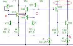
1) Q61 is superfluous or is there for some other reason not shown. The correct bias for Q5/Q6 is 0 Vce.
2) No, if you check the collectors of Q16 and Q17 are at the same potential, two Vbe's up from the top of I3. Q50 and Q61 are b to b diodes clamping the current mirror during slew. They are drawn as transistors because they are, the excess current during clamping action gets dumped out the supply which is often more benign.
3) No, Q15's and Q18's Cob are canceled by symmetry the same way this single stage gets Aol of 5,000,000.
I guess the schematic was pretty close afterall 🙂 Also to clarify again the term "neutralization" was probably inappropriate. The cap I call Cn is actually bootstrapped EXCEPT for the voltage signal across the output stage. So it amounts to a 1-A ~ 0 bootstrapping or positive feedback of the error.
Thanks Scott for explanation.
In the meantime I have got the circuit working by increasing I3 to more than 7mA, a rather high value. What's the real current, btw?
But now, most likely it doesn't work as intended, as Vce of Q17 is 0.33V higher than Vce of Q16 (i.e. unbalanced). On the other hand, if the collectors are at the same potential, then Q50 will conduct (because it shares the same Vbe as Q15 and the latter is certainly conducting). As a result, the circuit will heavily distort. So we have two choices: either Q50 is differently connected in reality or Q16 and Q17 should be operated out of balance (Vce wise).
As for NOT bootstrapping the collector of Q19, well, I got the lowest distortion if a took Q15 two times as large as Q19 and omitted Q64.
BTW, what's the role of Q64, just a clamp as well?
Anyhow, I'm afraid I'm still missing some important details like scaling factors and the correct settings of the current sources (and/or more specific details of the clamps).
Only a few values I was able to reconstruct: Q5=Q6=MAT02, I1=1.8mA, I6=0.35mA and beta of the other transistors is ~150, right?
Regards,
Edmond.
PS: I've no problem with the term "neutralization", it's all semantics and your description was clear enough to explain how it works.
Indeed A->1, but one shouldn't forget that it is still complex!
FrankWW said:So you didn't read it. Too bad.
It's a short article and wouldn't tax your intelligence. One take-away is that perception of linear distortion and non-linear distortion is not the same. Which, if you're in audio is likely a useful thing to know.
If you mean by linear distortions uneven frequency response, however it is perceived, and perceived differently than non-linear distortions. Uneven frequency response caused capacitances and resistances in amplifiers can be corrected electronically. Uneven frequency response caused by mechanical resonances can't be corrected electronically. You can shape measured curve, but you can't damp resonances.
Here is a driver I used in a tweeter array measured in the listening room, can you equalize it electronically? No. Even if to reduce amplification factor on resonant frequencies what to do with tails? It is one problem. Distortions are another one: resonances are more audible because of them. Tails and nonlinear distortions, 2 nasty things that cause audibility of "linear distortions" that cause more audible results of "linear distortions" on higher SPLs, when results of electronically caused "linear distortions" are less audible on higher SPLs. The later no doubt can be explained by perceptions, the former - not.

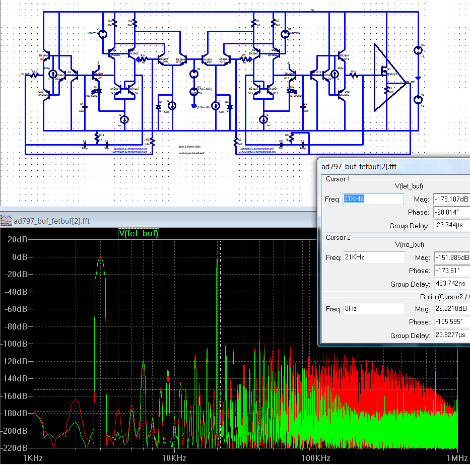
returning to ad797 "uacceptable 7th"
I've taken my simplified AD797 sim and put 300/10 Ohm feedback for +30dB gain with low noise contribution to see if the sim could shed any light on the 7th harmonic John's complaining about
to probe 7th harmonic/7th order nonlinearity I've chosen 1:1 3/20 KHz sines with a ~6 Vpp output as a stress level beyond mc preamp signal expected signal
21KHz is the 7th harmonic of 3K, it is low to begin with at -150 dB and reduced >25 dB by the really simple buffer in the loop (BSS145 with 600 Ohm bias giving ~20 mA Id)
2 KHz is the 1st order difference ( 20K - 6*3K ) from 7th order nonlinerities, ridiculously low unbuffered, lower still with the mosfet buffer
the largest difference is the 100K-1MHz higher order products which are reduced by the buffer
I believe the lower order products (2nd-6th, in decending level by order) in the sim are larger than expected from real AD797 - likely Scott's additional cascoding/buffering cures some problems of the simplified sim circuit
green trace is the output of the small signal mosfet buffered circuit, red is unbuffered
("butterflyed" duplicate simplified AD797 circuits, left unbuffered, right with simple small signal mosfet buffer both with my "T" compensation)
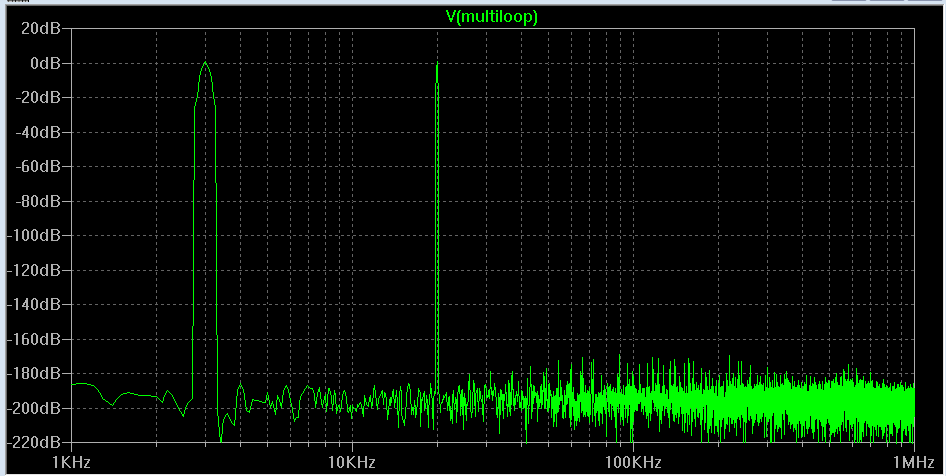
of course if you really wanted to minimize active device distortions in the audio frequency range I have a high feedback trick with a cfa output amp that gives this sim result with the simplified AD797 input, same load, signal:
I've taken my simplified AD797 sim and put 300/10 Ohm feedback for +30dB gain with low noise contribution to see if the sim could shed any light on the 7th harmonic John's complaining about
to probe 7th harmonic/7th order nonlinearity I've chosen 1:1 3/20 KHz sines with a ~6 Vpp output as a stress level beyond mc preamp signal expected signal
21KHz is the 7th harmonic of 3K, it is low to begin with at -150 dB and reduced >25 dB by the really simple buffer in the loop (BSS145 with 600 Ohm bias giving ~20 mA Id)
2 KHz is the 1st order difference ( 20K - 6*3K ) from 7th order nonlinerities, ridiculously low unbuffered, lower still with the mosfet buffer
the largest difference is the 100K-1MHz higher order products which are reduced by the buffer
I believe the lower order products (2nd-6th, in decending level by order) in the sim are larger than expected from real AD797 - likely Scott's additional cascoding/buffering cures some problems of the simplified sim circuit
green trace is the output of the small signal mosfet buffered circuit, red is unbuffered
("butterflyed" duplicate simplified AD797 circuits, left unbuffered, right with simple small signal mosfet buffer both with my "T" compensation)
of course if you really wanted to minimize active device distortions in the audio frequency range I have a high feedback trick with a cfa output amp that gives this sim result with the simplified AD797 input, same load, signal:
Re: Re: Re: AD797
Yes, I meant Q50 and Q64 are clamps for better post slew recovery.
I’m still a little confused. In my subset of your schematic, going from A to B there is a drop across R7, the Vbe of Q17, and the Vbe of Q15. Going from A to C there is the drop across R35, the Vbe of Q19, and the Vbe of Q18. These should be about the same unless the bias is way off so Q50 and Q64 have about 0 Vbe in normal operation. Q17 is not running at 0 Vce.
I’ll see if I can find the right currents.
Edmond Stuart said:
BTW, what's the role of Q64, just a clamp as well?
Anyhow, I'm afraid I'm still missing some important details like scaling factors and the correct settings of the current sources (and/or more specific details of the clamps).
Only a few values I was able to reconstruct: Q5=Q6=MAT02, I1=1.8mA, I6=0.35mA and beta of the other transistors is ~150, right?
Yes, I meant Q50 and Q64 are clamps for better post slew recovery.
I’m still a little confused. In my subset of your schematic, going from A to B there is a drop across R7, the Vbe of Q17, and the Vbe of Q15. Going from A to C there is the drop across R35, the Vbe of Q19, and the Vbe of Q18. These should be about the same unless the bias is way off so Q50 and Q64 have about 0 Vbe in normal operation. Q17 is not running at 0 Vce.
I’ll see if I can find the right currents.
Attachments
Re: Re: Re: Re: AD797
Scott,
Looking at the AES article schematic, I think one important missing detail is the transistors relative emitter areas. Relative emitter areas define, of course, the current ratios. Without that information, I certainly doubt one can calculate the bias using the AES article schematic.
scott wurcer said:
Yes, I meant Q50 and Q64 are clamps for better post slew recovery.
I’m still a little confused. In my subset of your schematic, going from A to B there is a drop across R7, the Vbe of Q17, and the Vbe of Q15. Going from A to C there is the drop across R35, the Vbe of Q19, and the Vbe of Q18. These should be about the same unless the bias is way off so Q50 and Q64 have about 0 Vbe in normal operation. Q17 is not running at 0 Vce.
I’ll see if I can find the right currents.
Scott,
Looking at the AES article schematic, I think one important missing detail is the transistors relative emitter areas. Relative emitter areas define, of course, the current ratios. Without that information, I certainly doubt one can calculate the bias using the AES article schematic.
Re: Re: Re: Re: Re: AD797
Yes, that's true but in most cases there is enough degeneration to lessen the difference. I found my netlist (1991) but the tools refuse to make a usable schematic. Maybe I should try C*****
(your former employer)


syn08 said:
Scott,
Looking at the AES article schematic, I think one important missing detail is the transistors relative emitter areas. Relative emitter areas define, of course, the current ratios. Without that information, I certainly doubt one can calculate the bias using the AES article schematic.
Yes, that's true but in most cases there is enough degeneration to lessen the difference. I found my netlist (1991) but the tools refuse to make a usable schematic. Maybe I should try C*****
(your former employer)
Re: Re: Re: Re: Re: Re: AD797
If it's spice netlist and there are no IP/NDA issues, you can send me the netlist. I did such conversions in the past.
scott wurcer said:
Yes, that's true but in most cases there is enough degeneration to lessen the difference. I found my netlist (1991) but the tools refuse to make a usable schematic. Maybe I should try C*****
(your former employer)
If it's spice netlist and there are no IP/NDA issues, you can send me the netlist. I did such conversions in the past.
Re: Re: Re: Re: Re: Re: Re: AD797
Thanks, fixed it with a little help from our CAD (there was a translator buried on a Solaris machine somewhere). I'll play with it tonight and put up some values for the current sources, you should be able to get a discrete version working (if it doesn't oscillate 🙂.
syn08 said:
If it's spice netlist and there are no IP/NDA issues, you can send me the netlist. I did such conversions in the past.
Thanks, fixed it with a little help from our CAD (there was a translator buried on a Solaris machine somewhere). I'll play with it tonight and put up some values for the current sources, you should be able to get a discrete version working (if it doesn't oscillate 🙂.
Re: Re: Re: Re: Re: Re: Re: Re: AD797
What about thermal tracking? 🙂
scott wurcer said:
Thanks, fixed it with a little help from our CAD (there was a translator buried on a Solaris machine somewhere). I'll play with it tonight and put up some values for the current sources, you should be able to get a discrete version working (if it doesn't oscillate 🙂.
What about thermal tracking? 🙂
Wavebourn said:
They are not, but cylindrical waves, relatively light diaphragms and heavy non-resonant in the band frames, tiny excursions, all factors help to reduce non-linear distortions caused by air pressure and deformations of surfaces. On high SPLs mechanical resonances are more audible not because of uneven frequency response (that presents on any levels), but because of non-linearities caused by deformations. This is my point. Some manufacturers are cutting costs on speaker constructions and materials trying to compensate resulting mechanical resonances by DSP equalizers, but that does not work as intended because making frequency response flatter they can't "equalize" distortions produced by speakers and their enclosures on resonant frequencies. Working in this direction I had to make very heavy speakers with complex shapes. It is costly and inconvenient, but so far it is the only way to go I see.
Edit:<snip> But what is desirable for musical instruments is bad for speakers.
Perhaps this is the incorrect thread for this discussion...but...
You've not made fair comparisons.
At high SPLs your argument: "but cylindrical waves, relatively light diaphragms and heavy non-resonant in the band frames, tiny excursions, all factors help to reduce non-linear distortions caused by air pressure and deformations of surfaces." fails because planars have equal or greater problems as do the usual "cone" type drivers.
It all depends on the specific range of SPLs that you are comparing. IF we compare only at the typical home listening average level (90-94dB SPL average at the listening position) then it is possible to make an argument that one can make small area dynamic speakers that have fewer mechanical resonances or distortions or certainly no more than an ESL - as the level climbs above that average level, then the dynamic drivers (not all of them, of course) keep going when the large diaphragm planars are in deep trouble with non linearities and break-up modes (there is a limited SPL and excursion capability).
The arrayed PA systems ("line sources") can be looked at per individual driver and cabinet - the array matters only in the far field for polar response. Here we see all dynamic drivers, and the occasional "ribbon" type - but while it is a ribbon/planar, it is small and not large.
Discussing the problems with manufacturers that cut corners, use DSP to cover up problems, etc. is another matter that has nothing to do with the absolute truths about this matter.
I agree that there is no way to satisfactorily filter out a mechanical resonance in any speaker system by electronic means (at least so far). The solution is always to find or build a better driver and avoid the basic problem first.
Oh, you call it a cylindrical wave from a planar - and if it is approximating this (at what frequency range?), the ear doesn't care since you are point sampling in space, what you do hear is the arrival times of the signal due to the height of the source, which tells your brain A) this is wrong, and B) I will make sense of it anyhow - which works out to be in effect that the point source has expanded and you are listening to it after some amount of expansion... but perhaps you are hearing it through two wide slits in a wall with the sound source on the other side... which might work out to be more "natural" to some people than listening to the same thing but this time through two portholes in a wall?
The shape of the wavefront, it seems to me, only really comes into play in two main ways (for home listening): the response on axis and the off axis response the other person listening hears; and also how the sound bounces off everything in the room... power response and all that stuff... which if it was an anechoic chamber would become irrelevant, but since real rooms are often the opposite it plays a big role in the perception of any given speaker in any given room.
_-_-bear
Re: Re: Re: Re: Re: AD797
That's precisely what I was already asking for. No need to ask this again.
syn08 said:Scott,
Looking at the AES article schematic, I think one important missing detail is the transistors relative emitter areas. Relative emitter areas define, of course, the current ratios. Without that information, I certainly doubt one can calculate the bias using the AES article schematic.
That's precisely what I was already asking for. No need to ask this again.
Well said, Bear. Most people don't realize that we have looked into this. The Wall of Sound by the Grateful Dead for example. A series array at 1 meter might be less successful.
john curl said:Well said, Bear. Most people don't realize that we have looked into this. The Wall of Sound by the Grateful Dead for example. A series array at 1 meter might be less successful.
I know John that you are looked into everything before everyone. But it is not an argument; an argument is that the less excursion to produce the same SPL is used the better linearity may be achieved. Bear writes well; he writes a poetry around all familiar words he reads in my posting, no matter relevant it is to what I express or not; it is as good as any poetry.
Yes, and I just talked to the guy who showed us the way to make cylindrical waves, instead of spherical waves, about 40 years ago, just today, Ron Wickersham. Worked with me at AMPEX in 1968. Today is part of ALEMBIC. We look at you as a mere child upstart, mostly because of your attitude toward us. You have good ideas too, but you don't seem to realize that many of us have spent man-years on projects using some ideas that you think are unique.
You see, we have lived longer than you, AND we had more money and resources, back in the '60's and '70's, so that we could pursue our projects.
You see, we have lived longer than you, AND we had more money and resources, back in the '60's and '70's, so that we could pursue our projects.
John;
I am disappointed by your telepathic abilities. You read my mind with very high level of non-linear distortions. Also, don't assume my telepathic abilities as good: I could not read mind of your friend who told you about cylindrical waves; I did not read mind of your another friend who made concrete horn under his floor; I did not steal their ideas. My ideas belong to me, and anyone is free to use them because the more I give to people the more God gives to me. The same ideas I am sure have other people. Many of them were thinking about waves in pools caused by thrown stones and sticks. You and your friends are not alone on the Earth, thanks God! Isn't it great, John?
However, some ideas can be already patented by somebody else who had them, so sorry people you can't use them for profit without paying royalties... "I ride my horse in this direction, it is mine, find your own and ride!"
We are happy John, you and me, and all your friends who deal with electronics, because nobody recently patented "A method of interconnecting of conductors using melted metals", otherwise we could not have our gear soldered sooo cheeeap! Browsing granted patents I am coming to conclusion that such a probability is high. 😀
"I Just spoke to The Man who Showed Us The Moon!" 😀
Anatoly,
Thanks for the compliment on my poetry. I have a license for that!
(that's a humorous comment: "poetic license")
Anyhow, I was thinking more about my comment on the cylindrical wavefront from a vertical source...
I had two other thoughts; Beveridge; and would vertical line sources be better if they reflected microphone pick up that maybe wasn't single point sampling? Dunno. Don't think anyone has done much on this yet...
There are some Germans who have implemented and have patents on multispeaker DSP controlled arrays that cover 5 surfaces of a room, or are used in arena sized events... interesting.
Look, I like John Curl, and you (and others) are just going to have to put up with the simple fact that at this point in time one gets to play the card that comes with seniority, experience and age if you had the luck/fortune/smarts to have been in some of the right places at the right time(s) - which he has. That credential also gives license to tell others from time to time that he can play the card. Which, John does...
In the words of Dr. John: "I was in the right place musta been the wrong time..." Being in the right place AT the right time isn't so simple looking forward, only looking back...
_-_-bear
Dear Bear;
I'm afraid all of us (including complete dumbies) have some times in past that force us to look back... First kiss, first candy, first car, first medal, first kid, ... We are not there now, both in time and in space... Somebody can miss that hardly and even drink heavily, but what's the point? Are we dead? Definitely not! Are we grateful? May be...
So, as an alive person who have bright moments both in the past and in the future (even though I am over my 50), I can tell you that it is a very interesting idea to have a room covered by speakers all around! It is flexible, at least! Any type of an artificial reverberation is possible there...
And you know what?
...I was dreaming of such a room with speakers and microphones all around, with controllable delay lines, being a kid! 😀
Well, I don't know what to say to that, but the idea behind this thread is to spread information about making better audio products. IF someone has a good idea, especially in electronic design, and it is presented here, well and good. If however, the same people think that they are the innovators of an idea that has been used for 30-50 years, I think this should be noted, even if it can be somewhat annoying or humbling to the individual who thinks it a new idea.
The most useful reason for this is to add what is already known, and not 're-invent the wheel' so to speak.
Each culture has its own strengths: American-British, Asian, Soviet sphere, European. We should learn the techniques unique to each culture.
However, each idea should be reviewed by others, in order to make sure that no oversights are made. This is important, because poor information is almost as useless as no information, and many of us have decades of experience, AND the technical references to make sure of the quality of the information. Those criticized by us, when necessary, should be grateful, rather than belligerent, for the added insight.
Sounds a little disingenuous to me.
If you were committed to spreading knowledge you would write a book. I think you are balancing between keeping your trade secrets under your hat and enjoying the conceit of playing the role of teacher in a public forum.
When a novice discovers something you think you have already discovered n decades ago, then to me they are just as much an inventor as you were and should be praised for cleverness rather than punished for repetition.
The thing you need to be careful about is the novice who uncovers the holes in your own theories. You really shouldn't have any holes after 50 years, right? Wrong. 7th harmonic! Some legend. 😉
Amidst all the bravado, you do provide a good deal of good quality information and tips and this is very beneficial. I try in my own way to dispel myth and show how to apply rigour; I do not tell all because even though I have no commercial interests in audio, I do not wish to give all my knowledge away.
😎
Re: Re: Re: Re: AD797
Hi Scott,
I think I've got it, that is, almost. Thanks.
So, for equal Vbe's of Q16 and Q17, VR5=VR7=VR9. Since R5 = 10*R9 it follows that IcQ19 = 10*IcQ16.
According to your paper (p.4) IcQ5=0.9mA and IR1=2.3mA. So IcQ16=IcQ17=1.4mA, consequently IcQ19=14mA and I3 = 14 + 2*1.4 + IR6 + IR8 ~=17.3mA. But now we have a problem, as the total supply current is far less: only 8.2mA.
Perhaps R9=37.5Ohms isn't that (unnecessary) small?
BTW, I'm still having issues with Q18: too much distortion. Apparently, it doesn't completely cancel the Early effect and Cob of Q15. Clearly, I'm overlooking something. Also the output stage doesn't perform as expected, most likely due to wrong settings of I4, I5 and wrong emitter sizes of the output transistors, but that's another story.
I really hope you can (and will) disclose more secrets of this beautiful op-amp.
Regards,
Edmond.
scott wurcer said:Yes, I meant Q50 and Q64 are clamps for better post slew recovery.
I’m still a little confused. In my subset of your schematic, going from A to B there is a drop across R7, the Vbe of Q17, and the Vbe of Q15. Going from A to C there is the drop across R35, the Vbe of Q19, and the Vbe of Q18. These should be about the same unless the bias is way off so Q50 and Q64 have about 0 Vbe in normal operation. Q17 is not running at 0 Vce.
I’ll see if I can find the right currents.
Hi Scott,
I think I've got it, that is, almost. Thanks.
So, for equal Vbe's of Q16 and Q17, VR5=VR7=VR9. Since R5 = 10*R9 it follows that IcQ19 = 10*IcQ16.
According to your paper (p.4) IcQ5=0.9mA and IR1=2.3mA. So IcQ16=IcQ17=1.4mA, consequently IcQ19=14mA and I3 = 14 + 2*1.4 + IR6 + IR8 ~=17.3mA. But now we have a problem, as the total supply current is far less: only 8.2mA.
Perhaps R9=37.5Ohms isn't that (unnecessary) small?
BTW, I'm still having issues with Q18: too much distortion. Apparently, it doesn't completely cancel the Early effect and Cob of Q15. Clearly, I'm overlooking something. Also the output stage doesn't perform as expected, most likely due to wrong settings of I4, I5 and wrong emitter sizes of the output transistors, but that's another story.
I really hope you can (and will) disclose more secrets of this beautiful op-amp.
Regards,
Edmond.
- Status
- Not open for further replies.
- Home
- Amplifiers
- Solid State
- John Curl's Blowtorch preamplifier