Edmond Stuart said:
Hi Jan,
He was addressing two issues:
1. Indeed, thermal runaway and/or current hogging.
2. A low bias voltage on only ~13mV, see:
http://www.diyaudio.com/forums/showthread.php?postid=1757356#post1757356
It is the latter to which I was referring. IF the amp is thermally stable with Vbias=26mV (and why not? D. Self has done it too), then switching to a lower bias will not make the amp less stable.
edit: Because this is rather obvious, I was wondering if there were other consequences like more THD, for example.
Regards,
Edmond.
Sorry, but D.Self has not done it on 90V rails in a >400W amplifier as far as I am aware, which is a completely different kettle of fish. And what is “stable bias”? The higher the rail voltage, the greater the Iq bias instability (an I do not mean thermal run away). D.Self has come under some criticism around these parts for allegedly underestimating thermal considerations in his “optimally” biased designs numerous times. How many times has Bob Cordell referenced his MOSFET amplifier paper regarding the Iq bias stability comparison between a MOSFET output stage and a BJT output stage?
This discussion stemmed from the claim that the output transistors in the JC-1 are operating in an “optimally” biased condition.
I contend that, for numerous reasons already mentioned, in normal operation this ideal may generally not be the case, particularly in the “low” bias mode.
Cheers,
Glen
Edit: And nowhere I have claimed that the JC-1 doesn't work or has "major issues", so don't regurgitate that red herring.
john curl said:In another case, we redesigned the heatsink internally to better balance the heat distribution.
Wow. But I guess that still had nothing to do with some of the irrelevant thermal considerations with such a design that I've been mumbling about.
Cheers,
Glen
as the point of optimum operating point is mentioned again...what about semiconductor aging?
Probably an audio amplifier is not replaced every two years as we do with mobile phones and computers.
Regards
Probably an audio amplifier is not replaced every two years as we do with mobile phones and computers.
Regards
Hi Juergen,
From where I sit, semiconductor aging isn't a big factor unless they get really hot. That's an entirely different thing.
I am in the habit of checking every power transistor (actually - all transistors) in every single amplifier I rebuild. I see more issues with differential pair mismatch than problems with output transistors. I am also measuring C-B and C-E leakage currents in addition to beta.
Once an originally black anodized heat sink is heated to a point where it becomes brown-black, or even yellow-brown-black, beta and leakage problems with any transistor mounted to that heat sink are likely to have shifted in their parameters. I will generally include these parts in any estimate since I can't trust them any longer.
What's your experience, or anyone else's?
-Chris
Hi Chris,
I don't have experience on this, except I remember 'gone crazy' varicaps or transistors in TV sets.
I'm just wondering about the accuracy working points and performances are specified here.
One could preselect parts for parameters or do adjustments in circuits, but what about after some years of operation? 😕
Regards
Cap Test update
I got stalled by a cascade of challenges (and earning a living) but a few observations I can pass along.
First getting a balance at parts per million will require ensuring that al the stray capacitances and resistances are balanced to that degree of accuracy as well. This sent me in circles until I "simed" it and confirmed that the probes at 10M and 10 pF across the caps if the caps are not identical will not get nulled out. What I was seeing on the scope matched the simulation almost perfectly. I'm waiting to get the opamp based test setup together but I still am concerned about balancing the stray capacitances.
I did a quick measurement of the caps on the CLT-1 and the Teflon was 20 dB better than the NPO MLC. A big difference. I will optimize and confirm my setup and publish some detailed numbers when I'm certain of what I'm looking at, however I'm not as confidant of the NPO's as I was. (The distortion is in the -140 to -160 dB range so it isn't much). The instrument is not convenient to operate right now so I'll get it sorted and document the results properly.
john curl said:What amazes me is that I have 100's to thousands of working amps out there, based on the principles that I have put forth here, recently. For some reason, they work pretty well, and measure pretty well, too. In any REAL design, there is some compromise. Yes, students, one must bend a little too get the unit to work for the majority of applications. My emitter resistors were originally 0.1 ohm, BUT we found problems with thermal runaway, so we moved them to .15 ohms. The Asian builders wanted to use .22 ohm, but I refused. It would have made things easier to build, BUT it would have exaggerated the Gm doubling, so highly thought of by Bob Cordell. I also use 10 ohm base resistors and this also causes problems, BUT it also prevents spurious oscillation with difficult loads, a useful tradeoff.
However, IF one actually got a JC-1 power amp and measured it, you would probably find that the Class AB-2 setting to be slightly lower than the marketing department states, and almost perfectly tracking with the .15 ohm emitter resistors. Still, the high current position sounds better, for most critical applications, and I recommend it, because the signal will not often go though the transition with real music, and even so, the changeover is not very noticeable as far as higher order odd harmonic production is concerned.
Hi John,
Thanks for this explanation. These are good points (and the JC-1 is a VERY good amplifier).
Cheers,
Bob
Good Demian, I thought so. Spoke to Bas Lim today, Teflon is 7 times more expensive than polystyrene.
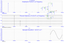
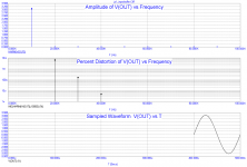
john curl said:PMA, do you mean the input follower?
I do not think so. What is the maximum input amplitude?
I would also suspect difference between Q5 and Q6 N and P MOSFETs.
Attachments
One could preselect parts for parameters or do adjustments in circuits, but what about after some years of operation?
I'm coming more and more to the conclusion that matching is grossly overestimated. If so, aging is also pretty irrelevant, at least in low power stages.
Have fun, Hannes
EDIT: before I'm flamed, let me clarify: I was referring to the usual IDSS/beta matching. Selecting for low noise or other parameters are another story.
I would not come to such a conclusion, except that I am glad that I use servos to make up for potential aging. Usually, devices just fail, however under EXTREME HEAT (100 degrees C or more over time), output devices can seem to just 'wear out'.
I would not come to such a conclusion
I think I shouldn't have posted my last post; it's too general and I guess one gets a wrong impression.
I was only refering to the impact of matching on simple specs like THD or distortion spectra. This is what I believe to be the main motivation for matching for most DIYers. Being myself one I was surprised to find out otherwise (so far).
Of course if one matches P to N-channel parts for low offset, that is something with an obvious advantage.
Or using selected low-noise parts.
Have fun, Hannes
It also depends on the application. I can imagine that with non-global feedback amps you need to be more carefull with the spread in parameters and the effects of (thermal) drift. With global nfb, those issues are much less important due to the linearizing effects of nfb, which also counteracts parameter spread, aging and drift.
So, YMMV 😉
Jan Didden
So, YMMV 😉
Jan Didden
Thank you, Bob Cordell, for your more detailed analysis of my output stage. It was informative, even to me, as I started to get sloppy with it, myself, but others should find it invaluable. It is an example of REAL ENGINEERING, or why we go to engineering school.
- Status
- Not open for further replies.
- Home
- Amplifiers
- Solid State
- John Curl's Blowtorch preamplifier