john curl said:However, IF one actually got a JC-1 power amp and measured it, you would probably find that the Class AB-2 setting to be slightly lower than the marketing department states, and almost perfectly tracking with the .15 ohm emitter resistors. .
AB-2? So in the low bias setting you're trying to maintain even less than 13mV across each emitter ballast resistor? Or is that what you call AB-1? Either case, on 90V rails with "almost perfect tracking" - Wow. I'll just assume all the transistors dies are always with in a degree or so of each other and current sharing is "almost perfect" too.
You must have an amazing Vbe multiplier.
Cheers,
Glen
alansawyer said:
Isn't the point that the signal goes through the transition on every cycle at relevant levels? How do you know the efficiency or listening level of the user? What am I missing?
Everything.
In case of push-pull 1A idle, e.g., you are in class A up to 2Ap output current, i.e. 16Vp output voltage at 8 ohm load. Unless the music signal peaks at the output do not reach 16Vp, you are in a true class A. The higher the idle current, the higher range of class A operation. In case of 100mA idle you pass always certainly into class B all the time, every wave.
PMA said:Everything. In case of push-pull 1A idle, e.g., you are in class A up to 2Ap output current, i.e. 16Vp output voltage at 8 ohm load. Unless the music signal peaks at the output do not reach 16Vp, you are in a true class A. [/B]
Yes, but how do you know the output level the user is going to operate at? To state that is wont occur for "real music" presumes you know what the user is going to listen to, and how loud. I don't see anything here that allows the designer to make that assumption, so I ask again, how do you know it will stay in class A? For an amp designed to use 90V rails and (800W?) output it may even be unlikely the user would not listen at high levels.
And for good manners PMA, I am not missing everything. That is logically incorrect.
john curl said:Yes, I do, I invented it, myself, 39 years ago.
No you don't, as there is no such thing. Even a Vbe multiplier with a “perfectly” matched temperature coefficient will not be able to respond instantaneously. The lower the quiescent voltage to be maintained across the emitter resistors, the greater the percentage Iq variation one has to accept under varying signal conditions.
Cheers,
Glen
Ref. output level of the listener - I certainly do not know, but I know the crest factor of well-recorded music and density of signal peaks. Also, at high volume levels, there is a considerable distortion of ear itself, and distortion of speakers rises fast. It is very important to keep lower volume level as clean as possible, rather than let it pass from A to B and trying to get lowest distortion at highest power - useless.
Perhaps the "nutters" with the silly SE tube amps don't look quite as wacked?
Yeah, they still do. With the high source Z, they're hot and expensive tone controls. The 1W distortion isn't very impressive, either. In another thread, one of the bright boys did some measurements which showed how microphonics can affect things when you actually have a DHT amp hooked to a nearby speaker. The point is often made that SE amps (whether tube or SS) could potentially cancel speaker distortion, but as a real-world possibility, I'm skeptical.
BTW, I'm impressed by the Ayre's noise and distortion spectra. Much more seventh than one would expect given John's high regard for the design (disclaimer: I have never used or listened to an Ayre product).
SY said:
BTW, I'm impressed by the Ayre's noise and distortion spectra. Much more seventh than one would expect given John's high regard for the design (disclaimer: I have never used or listened to an Ayre product).
J.A. tries to blame it on maths: "This is shown in a different way, as FFT-derived spectra, in figs.8 and 9. (Note that the higher-order
harmonics visible in these two graphs are almost certainly mathematical artifacts.)"
Also Charles spoke about maths and taught us about distortion residual shape. But - we can see higher harmonics also in a distortion residual plot, they appear as sharpening and kind of triangular shape.
Calculate MXR's idle current from idle input power, and the answer is here.
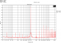
Note that the higher-order harmonics visible in these two graphs are almost certainly mathematical artifacts.
Unlikely. Unless they did some inappropriate windowing, and only did that for this particular measurement (since these "artifacts" don't seem to appear on other spectra they've published). One has to work pretty hard to create that sort of artifact.
Some insight, maybe more from a MOS-FET view, but I think still applicable...
http://www.passdiy.com/pdf/leaving_class_a.pdf
http://www.passdiy.com/pdf/leaving_class_a.pdf
zinsula said:Some insight, maybe more from a MOS-FET view, but I think still applicable...
http://www.passdiy.com/pdf/leaving_class_a.pdf
The numbers look pretty much better in 'peak power' than in rms power usually used 😀 😀
G.Kleinschmidt said:
No you don't, as there is no such thing. Even a Vbe multiplier with a “perfectly” matched temperature coefficient will not be able to respond instantaneously. The lower the quiescent voltage to be maintained across the emitter resistors, the greater the percentage Iq variation one has to accept under varying signal conditions.
Cheers,
Glen
John didn't claim perfect. You said "You must have an amazing Vbe multiplier".
His reply "Yes, I do, I invented it, myself, 39 years ago."
I have no problem with his statement. I haven't examined the circuit in question, but I do not see how you can make such a blanket statement. Even IF the circuit wasn't up to the level of your work, which I find very unlikely, he is still entitled to his belief that his design is very good or even amazing.
G.Kleinschmidt said:AB-2? So in the low bias setting you're trying to maintain even less than 13mV across each emitter ballast resistor? Or is that what you call AB-1? Either case, on 90V rails with "almost perfect tracking" - Wow. I'll just assume all the transistors dies are always with in a degree or so of each other and current sharing is "almost perfect" too.
You must have an amazing Vbe multiplier.
Cheers,
Glen
If it works satisfactory at Vbias=26mV, it will also work 13mV. Perhaps the current sharing is not perfect. So what? As a matter of fact, distortion is hardly affected, even when there is gross mismatch (-70%...+100%). And in some cases (i.e. equal Vbe spread of PNP and NPN devices) distortion is even lower.
Steve Dunlap said:
John didn't claim perfect. You said "You must have an amazing Vbe multiplier".
His reply "Yes, I do, I invented it, myself, 39 years ago."
I have no problem with his statement. I haven't examined the circuit in question, but I do not see how you can make such a blanket statement. Even IF the circuit wasn't up to the level of your work, which I find very unlikely, he is still entitled to his belief that his design is very good or even amazing.
Thanks for the complement. I'm entitled to my own opinion as well. Also, I was not implying that he did say it was "perfect". I was simply pointing out the fact that even if you can implement a Vbe multiplier with a temperature coefficient that very accurately compensates the output stage, you still have to live with the fact that it’s going to take a finite time to respond.
I think this is a relevant fact, particularly in regards to a power amplifier with such high voltage rails when low (0.1R, 0.15R) value emitter resistors are used in the output stage.
We don't care, Glen! 
As you well know, the proper application of feedback effectively "cures" all of these minor deviations of linearity?
Which is why there is not a smidgen of audible difference between any competently designed and built amplifier of sufficiently low "distortion."
Yes?
_-_-bear
As you well know, the proper application of feedback effectively "cures" all of these minor deviations of linearity?
Which is why there is not a smidgen of audible difference between any competently designed and built amplifier of sufficiently low "distortion."
Yes?
_-_-bear

Edmond Stuart said:
If it works satisfactory at Vbias=26mV, it will also work 13mV. Perhaps the current sharing is not perfect. So what? As a matter of fact, distortion is hardly affected, even when there is gross mismatch (-70%...+100%). And in some cases (i.e. equal Vbe spread of PNP and NPN devices) distortion is even lower.
And how do you guarantee a uniformity of NPN/PNP Vbe spreads or temperature dependent Iq sharing imbalances?
All I’ll say (partly from my own experience biasing high power output stages) is that 0.15 ohms is pretty low for an amplifier with 90V rails.
Cheers,
Glen
SY said:
Yeah, they still do. With the high source Z, they're hot and expensive tone controls. The 1W distortion isn't very impressive, either. In another thread, one of the bright boys did some measurements which showed how microphonics can affect things when you actually have a DHT amp hooked to a nearby speaker. The point is often made that SE amps (whether tube or SS) could potentially cancel speaker distortion, but as a real-world possibility, I'm skeptical.
BTW, I'm impressed by the Ayre's noise and distortion spectra. Much more seventh than one would expect given John's high regard for the design (disclaimer: I have never used or listened to an Ayre product).
SY, I agree that in practice that there are issues with tubes, be they class A SE or PP... I do not subscribe to the amp cancelling any speaker distortion(s), fwiw. In fact I don't even know what that is about...
Microphonics are an issue. Not terribly pertinent to the main concepts of spectra and distortions - put ur amps in an anechoic chamber?
I think that perhaps you are confusing the absolute level of distortion with the spectra of distortion, and the tube might look rather good compared to a SS amp going through the crossover point in terms of spectra? Beyond that single issue (how important is it in terms of listening?) there are clearly other major differences...
Otoh, if ur system is designed to "take advantage" of the output Z and other factors, maybe it works out ok? How about if it has a >100dB/1w sensitivity? Maybe things start to look a little better?
SY, I thought you were a "toobe guy"?
_-_-bear
- Status
- Not open for further replies.
- Home
- Amplifiers
- Solid State
- John Curl's Blowtorch preamplifier