I was using a modified version of the power gain stage I posted.
Hi, Steve,
Diamond voltage gain and diamond buffer output stage? There's a recent good reviewed power amp using these called "DartZeel"
http://www.diyaudio.com/forums/attachment.php?s=&postid=227250&stamp=1062004300
It also force classA on output stage, but by using forward diodes at base, so the base charge easy to come in and difficult to come out. Is this enhance classA the same result as your method (not using base bleeder resistor at all) ?
This has got to be the purdiest amp I have ever seen..
what artwork... I just simmed the circuit and it does the
hybrid class A thing.. WOW

Don't worry I dont need component values , just topology😀
OS
what artwork... I just simmed the circuit and it does the
hybrid class A thing.. WOW
Don't worry I dont need component values , just topology😀
OS
ostripper said:This has got to be the purdiest amp I have ever seen..
what artwork... I just simmed the circuit and it does the
hybrid class A thing.. WOW
Don't worry I dont need component values , just topology😀
OS
Their pre is somewhat more interesting.
I have used the same principle to avoid switches/relays in the signal path for years. If not for other reasons, then just to get rid of the ever returning issue of bad contacts.
Magura 🙂
Steve Dunlap said:That is not me, but yes I did fight harder when I was young. I still fought harder when I was old until I became a quadriplegic. That takes a little of the wind out of your sails.
[snip]
Sorry.... Bad joke.
Jan Didden
Hi,
do you think the chassis is a machined casting?
It can't be swaged, or could it?
Who made it? So we can all look at the pre (back on topic, well maybe).
do you think the chassis is a machined casting?
It can't be swaged, or could it?
Who made it? So we can all look at the pre (back on topic, well maybe).
AndrewT said:Hi,
do you think the chassis is a machined casting?
It can't be swaged, or could it?
Who made it? So we can all look at the pre (back on topic, well maybe).
the chassis is welded up from laser cut sheet, then machined.
It's a Dartzeel.
Magura 🙂
No clues how it all comes apart, but it doesn't LOOK to be easily maintainable.
No sour grapes - A very ineresting design and elegant implemetation.
No sour grapes - A very ineresting design and elegant implemetation.
I thought the amp was strange.. the pre takes the cake...
gel cells anyone... VERY good idea.. (+ - 24 V pure DC)
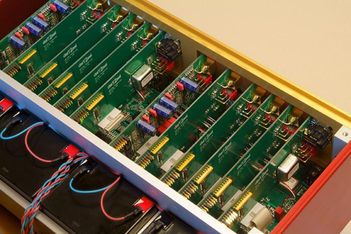
and PS..

The input select is called the "enjoyment knob" 🙂 🙂
gel cells anyone... VERY good idea.. (+ - 24 V pure DC)
and PS..
The input select is called the "enjoyment knob" 🙂 🙂
janneman said:
Sorry.... Bad joke.
Jan Didden
I think it's probably a good idea most people here go over to
Krill amp thread and digest carefully the OP stage Steve has
designed. It's actually quite brilliant and a breath of fresh air
compared to the usual offerings here.
T
Terry Demol said:
I think it's probably a good idea most people here go over to
Krill amp thread and digest carefully the OP stage Steve has
designed. It's actually quite brilliant and a breath of fresh air
compared to the usual offerings here.
T
I think Steve has designed a workable output stage that will make many DIY'res here happy and that is nothing to be critical of, however performance claims that, simply put, defy the laws of physics do not deserve to go unchallenged. Performance wise, I believe it to be inferior to a optimal biased D.Self double EF, and certainly incapable of the claimed linearity.
I also cannot understand why it is claimed that this OPS is “non-switching”, because it most definitely is not. I’ll explain one design issue with regards to this here as simply as I can.
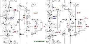
I’ve attached a part picture of the Krill OPS below. On the left shows a quiescent condition with the output voltage at 0V and the bias current set to 30mA as suggested. With the 0.22 ohm emitter resistors, this 30mA bias requires (simplifying with fixed 0.7V Vbe) +/-1.406V as the bases of the driver transistors. In other words, the bias generator needs to generate 2.812V.
The scenario on the right shows what happens when an audio signal comes along and the output voltage swings to 20V, causing 5A to flow through the 4 ohm load. The 5A load current flowing through R18 causes a 1.1V drop across R18. Consequently the emitter of Q14 is 21.1V and the base of driver transistor Q14 is 22.5V.
Now suppose we want to ensure that the PNP transistors do not turn off – for its emitter current to plateau at 30mA.
This would require the 6.6mV quiescent biasing voltage to be maintained across 0.22 ohm resistor R19.
So, that means that the emitter of Q16 will sit at 20V-0.0066V = 19.993V and the base of driver transistor Q16 will sit at (minus two Vbe’s) 18.593V.
Now here is the important bit. The bias generator now has to develop 3.907V between the bases of the driver transistors. This is over a volt greater that that required in the no-signal condition with the output at 0V (edit: simplifying here I haven’t added 6.6mV for the bias current to the 1.1V dropped across R18 by the load current).
Conclusion: a bias generator that can dynamically and accurately respond the audio signal and vary it’s potential to maintain that critical 6.6mV across the ballast resistor for the transistor not handling the load current is required.
First problem – there is a big fat 1uF capacitor between the bases of the driver transistors.
Cheers,
Glen
Attachments
Hi, Glen,
What about the excess charge that is left on Q14's base? Q13' emitor can give charge, but the remaining charge will keep Q14 on (when the PNP side starting to conduct), because there's no discharge resistor (from Q14' base to Q16 base or to output node). Q13's emitor cannot suck that charge, while only that connected to Q14 base.
What about the excess charge that is left on Q14's base? Q13' emitor can give charge, but the remaining charge will keep Q14 on (when the PNP side starting to conduct), because there's no discharge resistor (from Q14' base to Q16 base or to output node). Q13's emitor cannot suck that charge, while only that connected to Q14 base.
Originally posted by G.Kleinschmidt
I think Steve has designed a workable output stage that will make many DIY'res here happy and that is nothing to be critical of, however performance claims that, simply put, defy the laws of physics do not deserve to go unchallenged. Performance wise, I believe it to be inferior to a optimal biased D.Self double EF, and certainly incapable of the claimed linearity.
1. Your remarks belong to the Krill thread, not here.
2. Belief is one thing, while actual measurements and listening tests are different things.
Originally posted by G.Kleinschmidt
I also cannot understand why it is claimed that this OPS is “non-switching”, because it most definitely is not. I’ll explain one design issue with regards to this here as simply as I can.
There is at least one obvious mistake in your analysis, post it on the Krill thread and I'll respond.
My main question was with the distortion null. How sensitive is it to load? The resistive portion of a real speaker load can vary over an order of magnitude. Looks like a candidate for Jan's multi-tone test.
I can see why some simulators balk at this circuit. Some of the devices are in poorly modeled regions of operation. It's easiest to look at by forcing the output conditions and trace back to the point the rest of the circuit has to equilibrate at.
I can see why some simulators balk at this circuit. Some of the devices are in poorly modeled regions of operation. It's easiest to look at by forcing the output conditions and trace back to the point the rest of the circuit has to equilibrate at.
By GK - I also cannot understand why it is claimed that this OPS is “non-switching
I also doubted, But as LT is also based in physics (through
mathematical models) explain the (attached) OPS
simulations. 😕 😕
OS
Attachments
G.Kleinschmidt said:
emitter resistors, this 30mA bias requires (simplifying with fixed 0.7V Vbe) +/-1.406V as the bases of the driver transistors. In other words, the bias generator needs to generate 2.812V.
Cheers,
Glen
Glen, the output device goes from .03A to 5A (132mV delta Vbe). This cannot be simplified away in this case. OTOH if the quiescient bias voltage is modulated with output current one could argue technically that there is feedback, sorry 🙂 .
Hi,
we're back to that question: is calling it ClassA simply because a particular transistor does or doesn't pass current through the whole music cycle enough?
Most say no. Some say yes.
Glen and and others are awake I see.
This is a variation on ClassAB, it is not ClassA.
we're back to that question: is calling it ClassA simply because a particular transistor does or doesn't pass current through the whole music cycle enough?
Most say no. Some say yes.
Glen and and others are awake I see.
This is a variation on ClassAB, it is not ClassA.
- Status
- Not open for further replies.
- Home
- Amplifiers
- Solid State
- John Curl's Blowtorch preamplifier