KBK said:
Taking physics 'as-is' as a model to perfectly predict the future of technology advancement and physics is absurd as saying that you have journey in front of you and you don't know at all where it will take you, but you are laying a stick down in the sand that points in the direction you want to go--and you will not alter that direction of and in your journey --at any cost-- whatsoever.
You may chose to live without physics (or any other scientific discipline) as a way to understand and predict the reality, as much as you may chose to return to the caves and live according to your senses and subjective feelings.
I don't, as I find caves to cold and stinky to my (subjective) taste.
Good luck and stay warm.
john curl said:Getting back to the latest circuit: I think that paralleling input devices to get higher operating current is a good idea, even if not ideal, because of the added nonlinear capacitance. The original schematic was very clear, and laid out like a flower, which I prefer. The parallel schematic was initially confusing, partially because of how the paralleled input devices were added and because there were no crossovers. Still, it is a useful schematic, once we look it over carefully.
You are right.
Stinius
V-types would also be my choice, but as I mentioned before suggested configuration (see earlier posts) is merely for other types of JFets with less current margin.
Any useful comments/suggestions on the servo, John, Joshua, anyone?
Any useful comments/suggestions on the servo, John, Joshua, anyone?
john curl said:What was that for?
Perhaps he's referring to 'Les caves du Vatican' (André Gide) 🙂
syn08 said:
You may chose to live without physics
Physics is but an attempt to understand the world and the universe in which we live.
Joshua_G said:Concerning servo, a schematic was presented a while ago in this thread.
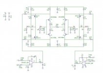
First is the line stage:
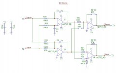
Joshua_G said:Next is the servo (however, I have no idea how accurate or effective it is):
Joshua
We have all seen these, and what is your conclusion if you compare these with the circuits that courage posted?
Could you give courage an advice regarding his servo?
That's what he's asking for.
Stinius
Joshua_G said:Physics is but an attempt to understand the world and the universe in which we live.
It's actually an attempt to describe the analog world in numerical form. The question always comes down to whether or not all the variables were captured.
MikeBettinger said:
It's actually an attempt to describe the analog world in numerical form. The question always comes down to whether or not all the variables were captured.
So far, as time go by, more and more variables are added.
As far as servos are concerned, there are only a few approaches, but numerous ways to connect the servo output(s) back into the preamp or power amp.
There are two types of servo, Common Mode, and Differential Mode, and they measure different things. Common Mode compares the AVERAGE DC offset of the 2 outputs to ground and forces the two outputs close to ground. Differential Mode offset compares the 2 outputs and forces them to be nearer each other. This is how I generally do it.
Others might separately take each side of the circuit and force it to be close to ground independently. Both approaches take about the same number of parts.
The details always drive me crazy, and I often get the phases wrong at first.
If you look at the JC-2 schematic in post 10520, you will see an example of a servo hookup, however with one resistor too many. I will report back when I remember which one (in the servo) should be removed.
John,
I have taken notice of the earlier posting with the JC-2 schematic + servo. However this configuration is quite different from BT "look alike" in terms of components and servo return points.
The possible options for the servo return points are:
1. at the JFets sources
2. at the Mosfets sources
3. at the Mosfets gates
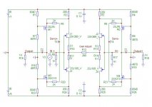
In the attached schematic the choice for servo return point at the Mosfets sources has been made, which to me gives the least instability problems and servos are according to what you described in your latest post.
As always comments/suggestions are welcome.
I have taken notice of the earlier posting with the JC-2 schematic + servo. However this configuration is quite different from BT "look alike" in terms of components and servo return points.
The possible options for the servo return points are:
1. at the JFets sources
2. at the Mosfets sources
3. at the Mosfets gates
In the attached schematic the choice for servo return point at the Mosfets sources has been made, which to me gives the least instability problems and servos are according to what you described in your latest post.
As always comments/suggestions are welcome.
Attachments
Looks pretty good, Courage. I like the servos.
However, could you reduce the 47 ohm bias resistors to 10ohms or so. It just won't work well with high value resistors and these jfets.
However, could you reduce the 47 ohm bias resistors to 10ohms or so. It just won't work well with high value resistors and these jfets.
Yeah.
I agree with John.
Looks good.
.... and Very Curlish a circuit 😎
----------------
* curlish; to be curlish
something that is very similar to the methods of John Curl, amplifier designer,
that lived in from the middle of 20th century to the middle of 21th century
I agree with John.
Looks good.
.... and Very Curlish a circuit 😎
----------------
* curlish; to be curlish
something that is very similar to the methods of John Curl, amplifier designer,
that lived in from the middle of 20th century to the middle of 21th century
lineup said:
* curlish; to be curlish
something that is very similar to the methods of John Curl, amplifier designer,
that lived in from the middle of 20th century to the middle of 21th century
I agree It's Curlish🙂
Stinius
My 'signature' is the flower pattern. I remember back in 1974 showing my future wife what I did. She played the violin at the Institute, but I just seemed to 'hang around'. I showed her my schematics and presented them as a pattern, rather than just a function. I suggested to her that it looked like a flower pattern, at the time, or 4 quadrant symmetry.
I don't think I will live that long, I am starting to feel 2/3 of a century old, truly. That's why you 'critics' should stop picking on me.
john curl said:My 'signature' is the flower pattern. I remember back in 1974 showing my future wife what I did. She played the violin at the Institute, but I just seemed to 'hang around'. I showed her my schematics and presented them as a pattern, rather than just a function. I suggested to her that it looked like a flower pattern, at the time, or 4 quadrant symmetry.
You like to work with symmetry?🙂
Stinius
- Status
- Not open for further replies.
- Home
- Amplifiers
- Solid State
- John Curl's Blowtorch preamplifier