janneman said:
That's great. Music is a very powerfull thing in life, and enjoying it can be very enriching.
Which is different from proclaiming to hear a difference or not between cables or caps or whatever. That's perception.
Jan Didden
I have a stereo setup which cost me a lot of money – almost beyond my means.
I paid that money for better enjoying listening to music, because of it's very important to me.
When I change a cable and my system sounds better and I enjoy more the listening – that's all I care about.
I know that there are people who don't hear any differences.
I believe I know some of the reasons for it.
However, I hear differences – and when something sounds better to me – that's all I care about.
I have no interest trying to convince anyone about audible differences between cables.
Nor am I going to argue with anyone about what kind of a fact is those audible differences.
Joshua_G, it is wonderful to have someone contribute with enthusiasm and not 'yet' tainted by the nay-sayers, that come out of the woodwork, every time a new idea is discussed.
When it comes to paralleling fets, sometimes it is good, sometimes it can make problems. What I used for the Blowtorch exclusively was high test 170V parts and their complement. NOTHING below 14ma Idss. This is approximately two 170Bl parts, so the Gm and Idss is not a problem, however NONLINEAR input capacitance is doubled. That is the tradeoff.
With a phono stage and source impedances below 100 ohms, paralleling makes good sense. Who cares about slightly higher input capacitance compared to paralleling for lower noise? However, with a line amp, paralleling COULD add distortion due to the volume control resistance in series with the input, that might be as low as 2500 ohms or as high as 25,000 ohms worst case. This could be a problem, and I have measured it with 2500 ohm worst case conditions. So, take care, everyone , on your design choices.
john curl said:with a line amp, paralleling COULD add distortion
Oh dear, adds another 8 FETs for Buffer the input-c slayer, makes one long back to the good old less than a Dollar per FET days.
(and Mr G. needs new eye glasses)
Attachments
scott wurcer said:It figures, I actually have amused myself with these sites off and on. I thought maybe a high profile failure might stir things up, maybe not. Even my alma mater's Tecnology Review gave the energy from water stuff the nod. I guess people are getting very desperate.
The lead is a guy named Randell Mills..as written by Bob Park,quote"" he was a 1986 graduate of Harvard Medical School. .... Two years later Mills held a press conference of his own to announce that it(cold fusion) wasn't fusion. It was better! Hydrogen atoms can shrink into "hydrinos," releasing energy""
They received a patent in 2000 for shrinking hydrogen atoms below the ground state. (6,024,935). The courts have basically rejected all further patents which defy the laws of physics..and have deemed 6,024,935 as questionable, to be withdrawn.
The origional company was HydroCatalysis Inc., back in '91. The name has since been changed to blacklight power. Apparently, they have pulled in 60 million in investor money since 91, and have yet to produce a product.
But they will have a prototype ready in 6 to 9 months..they just need more money, say...25 million more...they're soooooo close..
http://www.searchum.umd.edu/search?...&as_sitesearch=http://bobpark.physics.umd.edu
Cheers, John

jacco vermeulen said:
Oh dear, adds another 8 FETs for Buffer the input-c slayer, makes one long back to the good old less than a Dollar per FET days.
(and Mr G. needs new eye glasses)
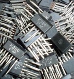
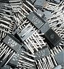
I will kill for some of this.

V types ... yummy
Attachments
john curl said:............ so it might well be an artifact in the measurement setup.......... Also, a transformer drive like the AP uses seems to ignore it as well. However, most audio equipment does not use transformers, so the 'distortion' still could be there with normal use.
Which is why the datapoints you have provided are valuable. Most audio equipment doesn't isolate as the AP does.
And again, good data points.john curl said:Still, it is repeatable for the same type of cable, especially cables with low usage. It can be very distinct with different types of cable, and some very expensive cables are actually worse than some very cheap ones. It will behave in the same manner with different ST analyzers, so it isn't necessarily a 'cold joint' or something like that.
The poorer measuring cables still have a low impedance return path, below easy measurement with a Fluke or HP multimeter.
I have dropped talking about the test, because it might well be an artifact of my specific test set-up, ....
Let's summarize (again, the last was several years ago.)
1. Your test setup finds distortion in the wires, a more sensitive and advanced test system does not. (recall Bruno Putzey's tests.)
2. You pointed out that the AP isolates via a transformer, this is a standard technique to break up a ground loop. (I dare say I bet they even use feedthrough caps).
3. You point out reception of tv scan frequencies among other things, this again points to a ground loop (these frequencies are magnetic coupled, not far field e/m waves..the loop impedance is very low (<<377 ohms), the wavelengths are far too long)
4. You point out a sensitivity to the cleanliness of the contacts. The ground loop you form has very low loop impedance, contact resistance is very significant as a result, sensitivity to it is an even larger pointer to ground loop.
5. You have now started the thinking of "it may be an artifact of your test setup". That is a huge statement.
john curl said:............ Perhaps it is better to 'put it to bed' until someone, somewhere, really wants to find why the different cables generate different distortion spectrums. That's OK with me.
No..you started it, you should finish it.
You have (inadvertently) put together a test method which clearly identifies a systematic problem typical of most audio systems, that of a ground loop susceptibility.
It is not about hum. It is about current paths. To wit, the safety ground we all use with NEC compliant equipment takes some of the shield current away from the IC's...that causes the shielding to be less effective (it is only 100% effective if all the current returns through the signals shield". Two IC's prevent that from happening at low frequencies. Two IC's and a ground? even worse.
You need to follow up on this. I gave you this stuff (actually, everybody) four years ago in hand drawings posted on the forums. I fully expected YOU to follow up, ask questions, and publish. It's your baby, go with it.
I STILL have, and refer to your cap articles. Good stuff, always said so..it's been too long.
Now step up to the plate, please...
You have always had my contact info. And I have offered many times..
The down side to you writing an article on this is,,,it could prove absolutely that IC's make a difference to the sound, it could prove absolutely that the PC's and wall socket can alter the sound, and it does so within the basis of resistance, inductance, loop geometry, and circuit analysis. It'll trash monocrystalline... grain boundaries, a lot of other stuff. But it will force the so called "naysayers" to sit up, take notice, listen to those who have said all along that there was a difference, and it will give them exactly what they need, a physics explanation that makes sense.
Several upsides, and several downsides...mixed basket of fruit..
Cheers, John
I'm sorry, Jneutron, but your explanations don't wash with me. You are just speculating, as you are prone to do, with other peoples work.
john curl said:I'm sorry, Jneutron, but your explanations don't wash with me. You are just speculating, as you are prone to do, with other peoples work.
No, I am not. I do this for a living. As does Tom Van Doren.
The only diffference for me, is I do it on scales significantly different from you, kilometers in length, microvolts from DC to 500 Mhz buried within a sea of 5 megawatt rf..on systems costing about 7 * 10e8 US dollars..
You don't have to publish this simple little audio paper, there are many others here who can do so.
I had hoped it would be you..
Cheers, John
Yah, I remember the last time you said that.. what, 4 years ago?john curl said:Jneutron, last time I looked, you wound coils for a living. Give it a break.
The antimatter confinement coil was the most fun...weird stuff, that is..where do they get these ideas..
Nonetheless, my current work is exactly what I spoke of.
As I said, go to Tom Van Doren, he will confirm exactly what I've been saying for the last 4 years to you. And he's been teaching it for 10 or 20 years now..
Cheers, John
ps...and the invite to my workplace is still there. anytime you're on the east coast..
Joshua_G said:
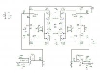
One thing is that you didn't parallel the JFETs, but double cascaded them. Cascoding them has no impact on neither current nor dissipation.
When I see a circuit that is both more complicated and by simulation of degraded performance, I will not go into the trouble of building it and listening to it.
I'm going to build an I/V stage based on JC's original idea.
You are welcome to build your circuit, no one is going to stop you.
However, if you claim that your circuit has any benefit over JC's basic idea – it is up to you to explain how your circuit improves performance.
They looked paralleled to me, just drawn funny?
>>– it is up to you to explain how your circuit improves performance.<< ??? If it sounded better to him would that be enough?
pssstt..john curl said:Jneutron, last time I looked, you wound coils for a living. Give it a break.
Update time.
Project 1.
Currently building/instrumenting seismic geophones to measure micron level vibration on a 5000 pound 4 testla magnet at liquid helium temperatures..geophones are a moving coil assembly, they are purchased for either horizontal or vertical motion. The optimal output impedance is about 5 ohms. It is necessary to run them differential twisted pair, from 4.5 kelvin to room, through vacuum, 20 meters or so, to a low noise diff input amplifier, band limited to 10Khz. 10 units in all. Two sit within 2 feet of a linear actuator, which will be used as active vibration cancellation. Shielding is interesting..ground loops are forbidden, as is the capacitance to ground problem of such a length of shield.
Project 2.
nanometer level active cancellation of a 500 lb beam focus magnet which sits within 1.8 Kelvin and 3 tesla solenoidal field. Same measuring devices, but actuator unknown.
Project 3.
Measurement of phase and amplitude of a 500 lb room temp magnet. Both phase and amplitude from 1 hz to 1 Khz. Using a kepco amp drive (4 amps peak), and a 20 turn coil made from #30 awg copper wire. Peak field about 30 gauss. Coil again differential input low noise stuff, with major worry of external noise. Oh, field has to go through about 1 inch of solid aluminum..
Phase has to remain below 5 degrees lag..or beam is lost.
OOh, where's my manners...
project 4.
Wiring layout of about 2 *10e6 dollars of wire, from 650kcmil to .200 mil microwave cable. My ground loop thread is actually a subset of what I'm putting together to measure/cancel the crosstalk between 50 meters of #10-3 at 1Khz 20 amps, and 4 twisted microwave cables that monitor beam position. We have a big issue with the microwave cable twist pitch and the #10 pitch, as they'll couple both common mode and differential mode magnetically as they are in the same cable tray..
Coil winding is still active, just not on the front burner...
You'd know all this if ya visited, dude..
Cheers, John
john curl said:Paralleling WILL give you more distortion with high Z inputs.
How about paralleling FETs for low Z input, like the output of a DAC which is current source?
scott wurcer said:
They looked paralleled to me, just drawn funny?
They are double cascaded – please look again.
scott wurcer said:
>>– it is up to you to explain how your circuit improves performance.<< ??? If it sounded better to him would that be enough?
Yes, should it sound better. However, right now it is claimed to be only a schematic, not an operating stage.
Joshua_G said:
How about paralleling FETs for low Z input, like the output of a DAC which is current source?
I'm sure John would be happy to answer this one

jneutron said:
Project 1.
Project 2.
Project 3.
project 4.
It is good there is someone to praise someone.
Joshua_G said:
They are double cascaded – please look again.
Joshua
Are you talking about cascode or cascade, I see you are using different words in different post. I think you mean cascode.
Maybe it is something I don’t see, so could you please tell me where you see a cascode here? And you are even talking about a double cascode.
Maybe JC can help you?
Stinius
Attachments
Many "experts" give their comments when an idea backed up by a schematic is presented. From some, we all know, I have never seen a circuit or simulation to contribute in a sensible way.
I am just trying to contribute in a constructive way. Not to give endless praise to some, post after post. After all we're not in church and it ain't sunday ...
Please take a good look at the schematic before commenting, because to me the JFETS are parallelled! It is a choice for those who are not able to come by the Toshiba V-type JFets. If however the configuration should be drawn differently for lower noise, then please show or explain clearly how.
Comments on the servo configuration are also welcomed. What can be improved here or what better approach is advisable.
Thanks
- Status
- Not open for further replies.
- Home
- Amplifiers
- Solid State
- John Curl's Blowtorch preamplifier