Yes I think most consumer gear is unbalanced but it usually doesnt matter. I come from a studio background where the gear is mostly balanced +4dbu but it can still hum like mad. You have to consider your service ground (the metal rod in the ground). Sometimes these are 10s of ohms and every induced ground current in the building runs thru it. Some times studios drive there own ground rods and run a seperate Tech ground to tech power outlets, but one poorly designed ground system in a box can tie them together. Ive measured hundreds of milivolts between these grounds!!
Sorry, I refer to the signal cables.I assume you refer to the power cords.
cbdb said:Yes I think most consumer gear is unbalanced but it usually doesnt matter. I come from a studio background where the gear is mostly balanced +4dbu but it can still hum like mad. You have to consider your service ground (the metal rod in the ground). Sometimes these are 10s of ohms and every induced ground current in the building runs thru it. Some times studios drive there own ground rods and run a seperate Tech ground to tech power outlets, but one poorly designed ground system in a box can tie them together. Ive measured hundreds of milivolts between these grounds!!
Under NO circumstances should what you call "service ground" be used as something to protect humans from excessive voltage on equipment chassis. You are referring to an earth ground, and as you point out, it can be in the 10's of ohms. NEC 250.64 requires the use of one additional electrode should the first exceed 25 ohms.
The scary part is, if the first is 100 ohms, they require a second..if that is also 100 ohms, you have 50 ohms to ground.(NEC does not require adding more and more rods until 25 ohms is reached. A fault which makes a chassis hot will cause 2 amps of current to flow to ground, this does not pop a breaker... Even if the earthed resistance is 25 ohms, a fault will still draw only 5 amperes...lethal circumstances since the breaker will still not pop..
That is why bonded real grounds are required, and they have to force adequate fault current to trip the safety device upstream.
It sounds like you need to call in a grounding specialist. I'd recommend T. Van Doren. (and no, I am not related to him, nor do I get credit for referrals..😉
cbdb said:
Sorry, I refer to the signal cables.
Ah, ok. What I did not mention, is that if you use two IC's, at low frequencies the return current shares, meaning the IC's form a loop as well...tying them very close together will help reduce induction.
Cheers, John
ps.. you do realize that the power company uses the earth as the neutral return for their three phase HV distribution system..Any imbalance in the 3 phase system FORCES earth currents to flow, and that creates voltage gradients within the actual earth. It is a (non trivial) thing to measure the actual earth potential over an area of property that is caused by the neutral currents. Anybody who uses seperate earth rods and assumes earth is at a constant potential, deserves the headaches they get...I'll send em an excedrin 300 count bottle...
jneutron said:
ps.. you do realize that the power company uses the earth as the neutral return for their three phase HV distribution system..Any imbalance in the 3 phase system FORCES earth currents to flow, and that creates voltage gradients within the actual earth. It is a (non trivial) thing to measure the actual earth potential over an area of property that is caused by the neutral currents. Anybody who uses seperate earth rods and assumes earth is at a constant potential, deserves the headaches they get...I'll send em an excedrin 300 count bottle...
Sounds like a very good reason NOT to live or work beneath a HV transmission line. I suspect there is a strong 60 Hz field between the lines and ground as well.
Thanks for the very clear presentation on the issues of grounding and ground loops. They are not as mysterious as some believe but not obvious in their origin and elimination. Adding isolation transformers and balanced connections may do nothing for the problem if its origin isn't clearly understood.
1audio said:Sounds like a very good reason NOT to live or work beneath a HV transmission line. I suspect there is a strong 60 Hz field between the lines and ground as well.
You have misunderstood a tad...my fault for not being clearer.
(I live on the east coast, we have one bushing transformers on the top of the poles...so my explanation is for that. Two bushing transformer service typical of the west coast is a bit different).
In the neighborhoods, if you look at the very top of the poles, you will see one wire at the tippy-top. That is a HV line. Below that, the transformer that drops the voltage to 240. Right below that is the neutral wire that supports the 120 pair that feeds the houses as well as provides neutral to the houses. That neutral also serves as the return for the hv that feeds the (auto)transformer of the pole. Every coupla poles, there is an earth return for that neutral. In other words, there will be current that flows in the actual earth as a result of the hv current. And you'll notice that there is only one wire....the power company sends only one of the phases down any street, and they have to balance the 3 phase system.So down ANY street on the east coast, there will be neutral return currents in the earth. It is divided between the pole neutral and the earth return.
Have your wife drive down a larger street...and look at the transformer hookups...at the very top will be 3 wires, and every transformer along the street will be connected to one, then the other, then the third...A, B, then C, then back to A. Balanced load.. cept of course the industrial hookups, they typically will have 3 transformers at the pole..
1audio said:Thanks for the very clear presentation on the issues of grounding and ground loops. They are not as mysterious as some believe but not obvious in their origin and elimination. Adding isolation transformers and balanced connections may do nothing for the problem if its origin isn't clearly understood.
Bingo.
Demian, don't you remember my asking what the biggest RCA jack size was, coupla years ago, for putting a toroidal current sensor over?
Dere ya go..now ya know.
Cheers, John
I believe it was. Very interesting class. He got me thinking!jneutron said:Was it Dr. Tom Van Doren by any chance?? Nice guy...
Regards, Mike.
jneutron said:
You have misunderstood a tad...my fault for not being clearer.
(I live on the east coast, we have one bushing transformers on the top of the poles...so my explanation is for that. Two bushing transformer service typical of the west coast is a bit different).
Bingo.
Demian, don't you remember my asking what the biggest RCA jack size was, coupla years ago, for putting a toroidal current sensor over?
Dere ya go..now ya know.
Cheers, John
We did miss each other on this. I was talking about 500KV distribution lines. After I read your note I took the dog for a walk looking at the poles here on the west coast. Your right- two bushing transformers and three wires at the top of the poles here.
The issues around voltage gradients and not using a ground stake as a safety ground cannot be emphasized enough. A consultant I worked with told me about a case in Florida he worked on where someone was electrocuted by, in effect, inadequate grounding from ground rods.
I have a collection of current probes for tasks like looking at ground currents. The most sensitive is the old HP 428 however its not that sensitive and a little clumsy to use. But it takes little current to degrade a ground reference. 1 mA of 60 Hz leakage (100K Ohms Z or 26 nF from a 120V source) across 10 mOhms, a very good connection will generate 10 uV, or enough to seriously degrade that ultra low distortion number. The
This is where the attention to detail and obsessive care in design and construction a DIY'er can commit that few commercial products can afford.
He is excellent. He came here and gave a two day class.MikeBettinger said:I believe it was. Very interesting class. He got me thinking!
Regards, Mike.
There were only two things in those two days that he was incorrect on. (back in my yoot, I'da called him on it in the class, but that would have served nothing..)
1..He stated that a twisted pair has coincident current centroids..they do not, but the centroids twist around each other at twist pitch, and the integrated centroids are indeed concentric. A nitpicking distinction normally.. But when you are driving a 500 lb accelerator magnet at 1 kHz and 20 amperes on a twisted 50 meter long #10awg, and in the same cable tray is a beam position monitor cable set with an identical twist pitch looking for microvolt signals within 5 feet of the magnet, it is very important that the cable sets not have an integral pitch relationship, as they will couple..Note that cat5e uses 4 twisted pairs that do not have integral twist pitches...they are what we call "orthogonal".
2. He stated that it was not possible to run a single ended signal from one side of a 25 foot wide room to the other without picking up noise...to wit, an RS-232 signal. Having run 100 foot single ended line levels in a 450 seat venue, I know it is possible (but requires attention to the powering and grounding scheme.
Yah, I realized that I left out a lot, so your thinking was certainly on the mark..1audio said:We did miss each other on this. I was talking about 500KV distribution lines.
I had checked it out from the car when I visited sanfran and napa(hmmm..somebody needs a "happy birthday" dude!!.), but I don't know if they also run distributed grounds from every second or third pole like we do on the east coast.1audio said:After I read your note I took the dog for a walk looking at the poles here on the west coast. Your right- two bushing transformers and three wires at the top of the poles here.
Actually, It's far more nefarious than you indicate.1audio said:1 mA of 60 Hz leakage (100K Ohms Z or 26 nF from a 120V source) across 10 mOhms, a very good connection will generate 10 uV, or enough to seriously degrade that ultra low distortion number
If you test a piece of gear on the bench using excellent test gear, that tells you how it works with "excellent test gear". But on the bench, the ground loops are not duplicated, the ground return impedance ratios are not duplicated, the induction coupling is not even presented to the gear...
Is it any wonder that some find a lack of correlation between bench measures and sound?? Honestly, I cannot discount the possibility..especially with low impedance solid state gear..
Now, if one assumes a ground setup as I detailed, and then introduces a wee bit of coupling between the amplifier line cord draw and that ground loop....then we are injecting odd harmonics into the input signal...harmonics that are related to the amplifier output power, the filter cap impedance(note 1), the supply bridge transfer function(note 2) (I/V relationship), the bridge snapoff speed, the transformer impedance...the entire power supply design both electric and geometric.(note 3).
Again, a coupling that does not exist on the test bench..
And this is only the first level issues.. It is rather more complex, but we must walk first...
Agreed. But the diyer absolutely needs to understand the theory to understand the corrections..1audio said:This is where the attention to detail and obsessive care in design and construction a DIY'er can commit that few commercial products can afford.
Hence the forums..
Cheers, John
Notes:
1..big caps lose their capacitance with frequency, a consequence of skin effect and build topology..proximity effect is a better term than skin effect, but that requires more explanation and I'm basically a lazy guy.....😀
2. Diodes vary in how fast they conduct vs voltage...depends on wafer resistivity, dopant concentration, wirebond resistance, epitaxial or not...lots of that technical goop...
3. How you layout the supply affects loop coupling..big caps are terrible to work around, and to the best of my knowledge, nobody tries to block current coupling effects between what feeds the caps and what draws from them..
jneutron said:He is excellent. He came here and gave a two day class.
Notes:
3. and to the best of my knowledge, nobody tries to block current coupling effects between what feeds the caps and what draws from them..
Cheers, John
The class I attended was a one day course and if memory serves me it had more of a system based focus, at least those are the details I remember. This was in the 1994-5 timeframe.
I'm curious as to what you're getting at in Note 3. Are you describing an inductive coupling or a physical (as in layout ) related interaction?
Regards, Mike.
....
3. How you layout the supply affects loop coupling..big caps are terrible to work around, and to the best of my knowledge, nobody tries to block current coupling effects between what feeds the caps and what draws from them..
A small thing, but I thought that is what 4 terminal caps were all about - an attempt to "Kelvin" the connections.
MikeBettinger said:I'm curious as to what you're getting at in Note 3. Are you describing an inductive coupling or a physical (as in layout ) related interaction?
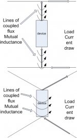
mutual inductance. And it would behoove the designer to work the physical layout in any attempt to minimize the mutual inductive coupling.
cliffforrest said:A small thing, but I thought that is what 4 terminal caps were all about - an attempt to "Kelvin" the connections.
Yes, 4 terminal caps were used to break the mutual inductance between before and after the capacitor.
4 wire works kinda like a kelvin circuit, but it is not an IR effect. Rather, it brings the common length of the circuit between input and output to the smallest possible..I drew both to show how the mutual inductance works, and how the 4 wire lowers it.
Cheers, John
ps...cliff...I was referring to audio. RF in da old days used 4 wire caps as a matter of course...(so I've been told, I'm not that old...😱 ....maybe Sy??
Cheers, John
Attachments
jneutron said:
There are many calculations that can be had, but unfortunately an analytical solution to a specific geometric problem will be beyond solving.
Cheers, John
I was just reading about a specific attempt at a particular type of quantum particle modeling and it requiring in the neighborhood of 200 trillion computations per second-or was that for the single computed interactive? This, for the most basic and nearly ineffective modeling of only the minimal aspects that MIGHT be useful. And that is only for a barebones quantum structure that is interactive. Now modeling interactives of a 'mass' of fluid dynamics?
Not gonna happen.
Like water we can predict (Victor Schauberg) the flow in some mass manner in some sort, but the issue here is that we are considering near/at quantum interactives so it's just not going to happen outside of some basic bit of 'grokking' on the individual's part, as you well know.
teraflops..200 teraflops.KBK said:I was just reading about a specific attempt at a particular type of quantum particle modeling and it requiring in the neighborhood of 200 trillion computations per second
.2 petaflops..
They have one of the QCD computers here. The issue is the number of dimensions and degrees of freedom. No biggy, just more variables in the equations... that's all.
KBK said:Now modeling interactives of a 'mass' of fluid dynamics?
You keep referring to E/M theory and modelling as fluids..I've no idea why anybody would attempt to do so... I've read the ramblings(as opposed to concise analytical derivations proofs, and results) of some of the websites that share these types of notions.......romantic notions, that's what drives those guys..perhaps someday they will be able to prove something, and meet King Gustav. Perhaps not. Years with no attempt at proof or refutation...
But for now, these problems could be easily solved classically.
Using Maxwells equations, it is a simplistic thing to derive any 3-D model, and predict it's behaviour to 10 decimal places..childs play with something like Roxio, matlab, Opera, or one of several other platforms.. We do it here everyday.
It would be trivial to input all the components of a piece of gear into a roxio model, and let the computer crank out the E/M fields, current densities, energy storage..but what good would it be to a hobbyist or even a designer?
The better methodology is to establish an understanding of the problem...things like how to control the current paths. Suprisingly enough, most of the top designers of the world do not know how to control the current paths.. That is why people like Tom Van Doren are so so busy travelling the world, detailing what exactly the issues are with respect to grounding and shielding.
That is why I provided a classical circuit analysis of a simple two box, three cord system.. This is the starting phase of a better understanding of why cordage can make a difference, even though common understanding is that it shouldn't..😱
Cheers, John
and ps...I do not sell wires.
jneutron said:
You keep referring to E/M theory and modeling as fluids..I've no idea why anybody would attempt to do so...
I guess you didn't get the memo. 😀
I don't want to debate E/M theory here. It just isn't that useful. How about low noise design, or something else?
john curl said:I don't want to debate E/M theory here. It just isn't that useful. How about low noise design, or something else?
Nobody's actually debating E/M theory John..
And actually, it is extremely useful. As my example shows, anyone who designs a single ended input or output device which meets NEC has ignored E/M theory, and as a consequence, has ignored the path the signal currents will take. This has HUGE consequences on low noise design. Consequences which I know YOU have never accepted willingly.
Take your distortion analyzer as an example. You have a cable under test which grounds at two points on one chassis, and yet you accept the reception of TV scan frequencies as "part of doing businesss".
If you understand where the currents in your rig and cable actually go, you could probably figure out how to reduce the reception of the external noise.
Model your analyzer exactly as I presented in a previous post, then you'll see what you've been missing...
Or borrow a current sensor toroid from Demian and put it over the cable under test...bet ya see some of the signal, that indicates loss of current path control.
So, in response...this IS about low noise design..
Cheers, John
ps...noise incursion as a result of single ended design is only a first level effect. The next level of complexity will also attack differential input systems.
I just came across an interesting talk given by Bill Whitlock at an London AES meeting. (don't know how I missed it for a year). He talks about wire both audio and power , he also spends some time on audio transformers.
The down side is the talk is 2 hours long and you have to have the 42 page Generic Seminar Template "Understanding, Finding & Eliminating Ground Loops in Audio & Video Systems" in front of to make any sense of what he's referring to.
http://www.aes.org/sections/uk/meetings/a0705.html
The down side is the talk is 2 hours long and you have to have the 42 page Generic Seminar Template "Understanding, Finding & Eliminating Ground Loops in Audio & Video Systems" in front of to make any sense of what he's referring to.
http://www.aes.org/sections/uk/meetings/a0705.html
Speedskater said:I just came across an interesting talk given by Bill Whitlock at an London AES meeting. (don't know how I missed it for a year). He talks about wire both audio and power , he also spends some time on audio transformers.
The down side is the talk is 2 hours long and you have to have the 42 page Generic Seminar Template "Understanding, Finding & Eliminating Ground Loops in Audio & Video Systems" in front of to make any sense of what he's referring to.
http://www.aes.org/sections/uk/meetings/a0705.html
Thanks. I don't know when I'd get a chance to watch the whole kittncaboodle..Bill's a great guy. From what I've seen of his work, he's definitely ahead of the curve..
I loved his adaptation using a 12 volt transformer/rectifier to drive ground current to find sensitivities.. I didn't get the sense that he was looking for inductive coupling however, just IR sensitivity of the chassis/ground star geometry.
But he's definitely worth it for anybody interested...I recall he had some papers available online, wasn't it Jensen?
Cheers, John
For the record, I have and still design products that operate at 0.4nV/rt Hz across most of the audio band for the last 35 years. For SOME reason, they do not pick up hum or significant noise, and they operate single ended. You are making a 'tempest in a teapot', or making a problem where there is little or none. Also for the record, my phono stages have a bass gain of 80dB, which is a lot more than most here have bothered with in their designs.
- Status
- Not open for further replies.
- Home
- Amplifiers
- Solid State
- John Curl's Blowtorch preamplifier