If you open the line stage piccy in PP and clean it up you'll have no problem to read the value colors off the Resista MK3's, including the ones of the two regulator devices.
If I may add, Jacco; I've seen schematics with wrong read and converted resistor values. Some resistor values vary due to tolerances in JFets/Mosfets used. A change in component values (resistors) affects the total design. In that regard it is not an easy DIY project. Apart from that the PSU, of which even the basic topology hides behind a veil, is of greater importance. However supplied schematics and simulations provide a basis to further explore, refine and in some instances take another, equal/better route.
We zijn in ieder geval van de straat en hopelijk nuchter
😀
syn08 said:...But if you keep insulting anybody that debates your axiomes, then expect no mercy in return...
...The CTC enclosures denotes a lack of understanding of elementary notions of EM field theory and practice and it's a waste of metal, manpower, energy and ultimately a rip off for the naive, but stinking rich, customers. The same shielding results could be obtained by using good industry practices and some common sense...
And your contribution is:
"1. Shielding: I never said I could do it better. How could I say such, if the target shielding performances are undefined?"
How then could you possibly say any of that without any target shielding performance deffinition.
"2. But, relatively speaking, any competent engineer could get the same results at probably 10% the cost and effort. Which of course will kill one of the essences of the CTC: to be outrageously expensive."
Are you a competent engineer? Many of us are interested in less axioms and more details supporting improved design practices.
"3. For all yearning for the CTC schematics, PCB's, details. If the miracle would happen, you would certainly be dissapointed."
Really? Would I?
"Let me put it in a more blunt way: engineering is expendable, marketing is not."
I guess that statement is supposed to explain where your comming from???
Sorry for not actually contributing. Like for many here, sometimes it's hard to even keep reading.

I had hoped for some real info, Syn08. I thought that I had missed something.
I make much cheaper designs, with twice as many parts, and they work too, but not quite as well as the Blowtorch.
In truth, while Bob and I attempted to make some income from each sale, we found, years ago, that it just wasn't worth it.
It is like trying to make a Porsche in your back yard. To do it right, you have to do it the hard way, by hand.
Thanks Jacco for the picture of the line amp. There it is for all of you to reverse engineer.
flg said:
And your contribution is:
john curl said:I had hoped for some real info, Syn08.
Sorry guys, as many other former contributors I'm done here. I have nothing to contribute that would interest you.
Happy dreaming!
courage said:hides behind a veil
Luku mi mati Franklin,
isn't that somewhat boring ?
Example : i'm still (re-)building a preamp that a company in CAN refers to as the ultimate flagship, probably more up Mr Popa's alley, does only a couple of ppm thd+n at 2V out.
The Brit-Canadians favor ease of logistics, so the power supply case houses 3 around the corner made Plitrons instead of Spongebob fancypants transformers.
Same same for the amp case(s), rather choose a flimsy and difficult to manufacture chassis with looks that appeals to the masses than a stirdy tank case that is both resonance and EMI/RFI free.
Definitely not the way how the designer had intended.
The thing doesn't even have one of those spring suspended massive copper sub-chassis as Naim does, or Goldimouth.
As they used to say down south in End-Courts : Let's DIY things better.
(Good thing i live near the bottom of the sea and have a boring-boring hobby that keeps me sober inside, despite the splitting headache from playing white wino at the Jappon restaurant behind hotel New York yesterday evening. Mmm,...and the $65 fine for forgetting the parking lot meter at 6ft distance from the vehicle.)
Sorry guys, as many other former contributors I'm done here. I have nothing to contribute that would interest you. Happy dreaming!
Our policy is that you may make your point , and you may make your same point occasionally, but It is time to move on.

Jacco, fa waka?
Boring, yes.... but there are many ways to skin a cat 😉. However your project sounds interesting too. And, try to keep sober even if the hobby is boring. My motto is DIYW (Do It Your Way) 😀
Tan boen mi matti 🙂
Boring, yes.... but there are many ways to skin a cat 😉. However your project sounds interesting too. And, try to keep sober even if the hobby is boring. My motto is DIYW (Do It Your Way) 😀
Tan boen mi matti 🙂
MikeBettinger said:Hi John,
I use a simpler magnetic field probe that has been quite educational. I might suggest a slight variation. Take the NEC connections out of the picture and study the currents circulating on the grounds between components (say between an amp and a preamp), note what happens to them once they enter a chassis. The interconnects shields are the normal path inside (the NEC ground can confuse this) but, as I'm sure you know, once inside the chassis the currents tend to choose their own path.
Yah, the currents always choose the path of lowest impedance. What is interesting is when one learns what the low impedance path actually is..to many, it's counter-intuitive..
MikeBettinger said:Many years ago I took a class on grounding and shielding in which I witnessed a demonstration with a magnetic field probe that showed the return path of a signal completely ignoring a solid metal bar shunting the shield on a loop of coax and following the coax shield instead; definitely not the intuitive result. Another demonstration traced the return path of a signal trace over a ground plane which showed the return current concentrating under the signal trace. Regards, Mike
Was it Dr. Tom Van Doren by any chance?? Nice guy...
As another said, National Electric Code.bear said:NEC = ??
Unfortunately, the requirements to bond all chassis to a safety ground forces us into the position of worrying about ground loops. Ground loops caused by safety bonds are by nature low impedance, so even the attempt to measure them can change them. Low impedance ground loops can be altered simply by disconnection of the offending conductors by unplugging and re-plugging. And in general, attempts to measure the equip within the lab does not repeat the problem..
cbdb said:I thought magnetic shielding was best with mu metal? And the non magnetic materials were awful
Mu is quite good, but it will tend to saturate at low fields. In addition, bending it too much ruins the permeability..
Cheers, John
Bonsai said:Are ther e some calculation s that can show the effect on a signal in a wire running next to these different materials - for example a Phono signal ?
There are many calculations that can be had, but unfortunately an analytical solution to a specific geometric problem will be beyond solving.
Generics:
1. A typical shielded cable that is not bent tighter than five diameters will have zero external magnetic field, so proximity to metals of any kind will have no affect within the audio band.
2. If a shielded cable in a circuit has additional DC paths from one end of the shield to the other, the current flow will not be as expected. For example, if one uses a full ground plane on the PC board, and runs a shielded cable from one end to the other, the DC ground current will go through both the plane and the shield, ratio based on actual DC resistances. THIS means that for low frequencies, typically below approximately one khz, the shield is not shielding and the hot wire to ground plane has formed an inductive loop...which will pick up internal magfields of the enclosure as well as external magfields in the low audio band. It is only in the upper audio band and higher that the shield will get it's effectivity back.
3. This effect will also be present if one runs a pc trace over a ground plane...if the trace is not straight line, at low freq it will form a loop, and as frequency climbs over a Khz, the return path will be closer and closer to the signal trace.
4. To get some measure of what the geometry looks like electrically, measure it's loop inductance to the ground, from 20 hz out to 100 Khz. If you make the system with two ground connections, break one and insert an inductance meter. Or as an alternative, break one and inject a current signal into the ground and measure the resultant induced voltage on the signal wire.
5. Two effects happen when a wire carrying current gets close to a metal of any type..
a. Dissipative loss. This is a simple loss of signal as a result of eddy dissipation in the metal. It does not introduce a phase shift to the drive current, but will be frequency dependent, getting worse as freq goes up.
b. Phase shift....if the geometry of the external metal is such that current loops form and store magnetic energy, then this energy gain and loss occurs 90 degrees lagging. Because it is coupled to the primary current, it will cause a lagging phase shift.
I suspect that "b" is the most significant effect in terms of internal layout considerations.
But to put actual numbers in to an arbitrary design configuration is not to be reasonably achieved without a major software package.
Cheers, John
jneutron said:
Yah, the currents always choose the path of lowest impedance. What is interesting is when one learns what the low impedance path actually is..to many, it's counter-intuitive..
Does it follow only the path of lowest impedance?
or all paths proportional to their impedances?
myhrrhleine said:Does it follow only the path of lowest impedance?
or all paths proportional to their impedances?
Your excellent question was answered in the subsequent post:
""2. If a shielded cable in a circuit has additional DC paths from one end of the shield to the other, the current flow will not be as expected. For example, if one uses a full ground plane on the PC board, and runs a shielded cable from one end to the other, the DC ground current will go through both the plane and the shield, ratio based on actual DC resistances}.""
Cheers
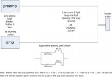
Now, a simple example.
Amp, preamp, wall outlet.
#12 awg grounds for both amp and pre line cords, spaced 12 inches apart and 6 feet long (entirely arbitrary numbers of course...)
belden 1855A for the IC. 6 feet long. Again, arbitrary choice.
I put the calcs on the pic, hope it comes out in the jpeg...
Note that at DC, the current on the 1855 shield is about 33% of the total, 66% of the return current will go through the safety ground. This means that the entire loop formed by the IC and the line cords will be capable of generating voltage as a result of faraday's law of induction applied to that loop.
At very high frequency, essentially all the ground current will go through the 1855A shield, and the proximity of the shield will prevent induction of voltage via faraday's law of induction.
The break frequency where the bulk of the return current goes through the shield can be easily modelled by using the provided numbers.
Note that this is a simple construct, and not an actual case. But the concept is the important thing here.
Cheers, John
ps...Belden does not provide the inductance of the 1855A, so I had to calculate it from the prop speed and the capacitance per foot..they make it using foamed HDPE insulation. From the numbers, foamed HDPE has a dielectric coefficient of 1.48.
Attachments
I guess the signal neutral in the cable also forms a grnd loop if a ground plane connects the ccts joined by the cable.
I'm not sure I understand your question.cbdb said:I guess the signal neutral in the cable also forms a grnd loop if a ground plane connects the ccts joined by the cable.
John
Maybee I dont understand your point. Are you talking shields on cables inside a preamp connecting different internal ccts?
cbdb said:Balance your connections. Fix most of your ground loops.
1.. I've always said balanced is best.
2. It doesn't fix everything. Ground loop currents can still flow, and if so, they must be considered.
I've run unbalanced line levels over 100 feet in extremely hostile e/m environments, and have easily prevented noise intrusion. It's all in the equations...😉
Your advice unfortunately, helps about 5% of the consumer marketplace (wild guess of course, I've no idea how many actually use balanced).
The best thing to do is understand the concepts.
John
cbdb said:are these cables 2 conducter (hot and neutral)?
I assume you refer to the power cords.
The National Electric Code, article 250 covers line cords for us in the USA....to wit:
250.4 (A)(3) Bonding of Electrical Equipment...
Normally non current carrying conductive materials enclosing electrical conductors or equipment, or forming part of such equipment, shall be connected together and to the electrical supply source in a manner that establishes an effective ground fault current path.
250.4 (A)(4) states: Normally non current carrying electrically conductive materials that are likely to become energized shall be connected together and to the electrical supply source in a manner that establishes an effective ground fault current path.
If one considers only the neutral, the problem changes significantly in that the neutral connects to the ground at the service panel. But for my drawing, one has to include any impedances to ground within the equiv model..
Cheers, John
- Status
- Not open for further replies.
- Home
- Amplifiers
- Solid State
- John Curl's Blowtorch preamplifier