1audio said:I thought you could get opto coupled transistors- essentially power mosFETs with photosensitive gates.
I'm not sure how your design is less sensitive to ground currents. And getting the isolation for the floating 10V supplies is a challenge unto itself. The DC-DC converters have some capacitance in to out and lots of noise.
I'm not sure its worth going into more details on the first Spectral amp (the CPU 1). Its ancient history.
We use PhotoMOS opto-couplers all the time, but the MOS output transistor is not a power transistor. They are convenient, but I don't think they are nearly as cheap as BJT opto-couplers.
Cheers,
Bob
bear said:Dead link? Got pulled? _-_-bear
<<http://www.ne.jp/asahi/sound.system/pract/eparts/34degawa-final.pdf>>
<<http://www.hint.no/utdanninger/iu/linker/datablad/IL300.pdf>> Check these out. They compensate for the inherent non linearity of the opto-coupler. I've used them to couple analog sensor outputs where isolation was needed.
anatech said:Hi,
Nakamichi used a novel approach (to me) for local regulation. They worked to keep any currents returned to ground as small as possible.
For example, the ground connection from the regulator circuit went to the emitter of a transistor. The collector was connected to the opposite "raw" regulated DC line. The base of this transistor was connected to ground. This reduced the reference currents to ground by the beta of the transistor and passed the bulk of the current to the opposite supply before the other regulator.
The end result was a very quiet ground and it made a difference that was audible. This was also a lesson well learned as soon as I grasped what they were doing.
Now a question on signal relays. Why not use a DC bias (from a very clean source) to establish the audio path? This would eliminate capacitors and allow a single supply to be used. A "ground reference" could be used for common connections. Either that or build the circuit as normal and pass current to ground or the negative supply. I favour sending current into a ground reference over involving a supply rail.
Just a thought, not necessarily useful or practical. This is why telecom circuitry does this though, to minimize the effect of less than perfect contacts.
-Chris
if I get what you are saying correctly, the motional mass characteristic alters the sonics in a very audible and derogatory manner.
Mike, those 'linearized' optocouplers look very interesting, and could be very valuable in certain situations.
john curl said:Mike, those 'linearized' optocouplers look very interesting, and could be very valuable in certain situations.
Hi John,
My audio related interest was as a way to interface my line out on my computer with my preamp for copying records to my hard drive. When I hooked up directly the sound from the main system sounded dirty until I pulled the cables to the PC. With the opto's in place it stayed clean. I haven't done any triple blind testing 😉 , but it makes the transfer of my 30 year old vinyl sound good in my car CD player on my way to work...
They are used in one of my sensor PLC's (Moore Industries) as a way to optically couple analog signals into the AD converters without grounding issues.
Regards, Mike.
Dennis Feucht has a nice design, specs:
high-speed: ³ 100 kHz; 150 kHz -3 dB bandwidth typical
high-linearity: 0.02 % THD at 1 kHz; 0.1 % at 30 kHz, 1 V pk-pk out
large dynamic range with low distortion; < 0.5 % THD for 5 V pk-pk input
250 ppm/°C drift typical
nominal unity gain; independent output gain (scale) and offset adjustments;
300 V isolation minimum, limited only by optocoupler ratings
low manufacturing cost: < $10 parts cost
uses differentially-driven linear optocouplers (LOCs)
unique dual-path feedback topology reduces THD caused by LOCs by x 20
feedback paths from differential LOCs cause error cancellation
I have a copy somewhere but can't find it now. More at www.innovatia.com, Dennis' website.
He also uses the IL300 IIRC.
Jan Didden
janneman said:Dennis Feucht has a nice design.
I have a copy somewhere but can't find it now. More at www.innovatia.com, Dennis' website.
He also uses the IL300 IIRC. Jan Didden
Thanks Jan,
The website is not working for me right now. The challenge to working with these is the need for independent supplies for the op-amps on both sides of the couplers. In my application the preamp side was easy and I opted for a 24vdc wall-wart supply and a DC-DC converter to get the +/- 15 for the input side. I didn't want to use the PC supplies, yet I wasn't shooting for high-end results.
Mike.
1audio said:"Derived ground"
I'm using a similar supply architecture in the NuForce P9 (and the upcoming G9) so that there is no ground connection between chassis except the shields. Each amp floats except for the single ground connection that the input, output and center of the shunt regulators reference to.
The goal of this is to minimize ground currents. I try to balance all of the DC currents so there is no DC flowing back to ground. its never perfect but it seems to just help both in lower measured noise and better sound.
1audio said:The supply floats and is external to the box. It's a current source with as high an impedance as I can make it. Internal to the box I further isolate it with resistors. The stacked shunt regulators define the regulated voltages. With luck there is very little dc going to the center of the stacked shunt regulators. The local supply caps should be large enough to support the peak current requirements of the load.
Hi Demian,
I've been thinking about your description and understand what your doing now. It's definitely a unique approach relative to my experience and from the reviews of the P9 posted on the web it works too. I'm sure, as they say, the devil is in the details.
I was interested in the descriptions of the shielding that I read and it made me wonder if your using a center tapped transformer and where you're connecting the shields into the ground system. In the supply/ control box or in the amplifier box (where the input and outputs connect to the rest of the system components)?
Regards, Mike.
MikeBettinger said:
I was interested in the descriptions of the shielding that I read and it made me wonder if your using a center tapped transformer and where you're connecting the shields into the ground system. In the supply/ control box or in the amplifier box (where the input and outputs connect to the rest of the system components)?
Regards, Mike.
The supplies are all floating with no connections to anything and the shields are tied to the ground references in the analog chassis at the connector plane. Its not ideal but it works within the constraints of normal audio practice.
flg said:
Thanks, I had one comma too many on the URL...
Jan Didden
janneman said:
I have a copy somewhere but can't find it now. More at www.innovatia.com, Dennis' website.
He also uses the IL300 IIRC.
Jan Didden
janneman
I started this thread 31 january 2003:
Audio Signal Isolation Techniques - Analogue Optocouplers
http://www.diyaudio.com/forums/showthread.php?threadid=10580
In the very first post I attach a short description of TIL300
which is the Texas name for IL300
Attachment:
http://www.diyaudio.com/forums/attachment.php?s=&postid=121254&stamp=1044033991
At the time, soon 6 years ago, wasn't much interest.
But sometimes, sooner or later,
people will catch up and discover good ideas of the possibilities for creative audio designs.
Lineup 🙂 regards to Jan
Hi Lineup,
Yes, interest is there, but if you see what Mr Feucht had to do to linearize those opto-couplers to get a reasonable linear performance over the audio band, that interest will quickly die, I predict! IIRC there are at least 3 optocouplers and 6 opamps. For one channel. Opamp haters will have a field day!😉
Edit: 2 x TL300A, 6 x opamp...
(I paid for the design package, Mr Feucht lives from his designs, so I'm not going to publish a copy here).
Jan Didden
I wrote 'linearized' because I am relatively sure that the 'linearization' is relative, and not perfect. Some applications require some sort of isolation to operate at max performance. I suspect that for servos, for example, or bioelectronics, this could be a wonderful solution. I doubt that this would replace a quality transformer for the audio bandwidth, however. The problem is often due to the distortion residual that is left after subtraction. If it is higher order, then the distortion is effectively still going to be audible when using this device.
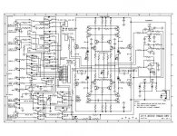
If there is nothing more to say about 'isolation' we might talk about the differences between the Parasound JC-2 and the CTC Blowtorch. As many may be aware, the Parasound JC-2 has won a fairly respectable position in both 'Stereophile' and 'The Absolute Sound' even though Parasound does not advertise in either publication. The 'heart' of these two preamps were designed by the same CTC design team. However, the design decisions were different, and the cost per feature is very different. It is very much like the difference between a Porsche 944 and a Porsche 911, in design tradeoffs. More later.
JC-2
That would be of great interest.
From the more or less correct BT schematics flying around here compared to JC-2 schematics I got from some of the persons hanging around this thread, it seems the JC-2 uses more transistors (JFETs).
I would like to here more about how and why the Blowtorch sounds better than a more complex design, and why the JC-2 has to be more complex.
Also, if I remember the JC-2 schematics flying around, it has negative feedback as well.
Regds
Rolv-Karsten
john curl said:If there is nothing more to say about 'isolation' we might talk about the differences between the Parasound JC-2 and the CTC Blowtorch. As many may be aware, the Parasound JC-2 has won a fairly respectable position in both 'Stereophile' and 'The Absolute Sound' even though Parasound does not advertise in either publication. The 'heart' of these two preamps were designed by the same CTC design team. However, the design decisions were different, and the cost per feature is very different. It is very much like the difference between a Porsche 944 and a Porsche 911, in design tradeoffs. More later.
That would be of great interest.
From the more or less correct BT schematics flying around here compared to JC-2 schematics I got from some of the persons hanging around this thread, it seems the JC-2 uses more transistors (JFETs).
I would like to here more about how and why the Blowtorch sounds better than a more complex design, and why the JC-2 has to be more complex.
Also, if I remember the JC-2 schematics flying around, it has negative feedback as well.
Regds
Rolv-Karsten
the differences between the Parasound JC-2 and the CTC Blowtorch.
okay.
😎 so you post at least a conceptual diagram of them both 😎
you know, without any component values .. even without transistor names, if you like
It is not very easy for the general public to talk about what only the few knows
If you want to talk we can, unless you make it impossible
and you like to keep discussing above our heads
with those few
those that 'knows it all' ... more than me & most diyaudio members at this forum
Lineup 🙂 thinks maybe Mr Curl had in mind we all should
rush to buy each our own Blowtorch and Parasound JC-2
in order to be able to discuss the differences
John,
can you give me an advice, please.
I want to find one N-JFET that has got VGS 2-4 Volt for like 1-5 mA
and that will work reasonably well at VDS >= 20-25 Volt.
Is for input stage.
I have used 2N3819 (rated 25 VDS) at VGS 2.20V and 0.80mA.
But you have any other suggestion?
thanks 🙂
Lineup
can you give me an advice, please.
I want to find one N-JFET that has got VGS 2-4 Volt for like 1-5 mA
and that will work reasonably well at VDS >= 20-25 Volt.
Is for input stage.
I have used 2N3819 (rated 25 VDS) at VGS 2.20V and 0.80mA.
But you have any other suggestion?
thanks 🙂
Lineup
lineup said:
okay.
😎 so you post at least a conceptual diagram of them both 😎
you know, without any component values .. even without transistor names, if you like
It is not very easy for the general public to talk about what only the few knows
If you want to talk we can, unless you make it impossible
and you like to keep discussing above our heads
with those few
those that 'knows it all' ... more than me & most diyaudio members at this forum
Lineup 🙂 thinks maybe Mr Curl had in mind we all should
rush to buy each our own Blowtorch and Parasound JC-2
in order to be able to discuss the differences
Here is a JC-2 I had around. Correct? I do not know. OK to publish? Do not know, but as JC wished for a discussion I believed it was.
The BT concept has been around here enough times I believe.
Regds
Attachments
- Status
- Not open for further replies.
- Home
- Amplifiers
- Solid State
- John Curl's Blowtorch preamplifier