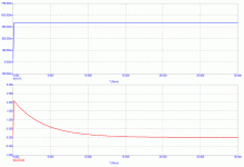
john curl said:I normally use 1 meg ohm and 1uf for a time constant of 1. .
Yes ... but ... the resulting time constant of the whole circuit depends also on resistive network behind the opamp. I mean e.g. divider created by series resistor behind opamp output and by -IN resistor to ground. If it was 10:1, resulting time constant would be 10x higher.
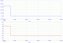
I prefer to use a 50 ms one sided pulse, and note the tilt and DC shift. Either way gives info.
x-pro said:
Jan,
That is exactly what the servo does, and if this offset present for long enough the servo output goes out of range and trips the protection. That what my circuit does and Bob is apparently using a similar approach. Obviously, the servo may fail but so may the protection circuit itself and after all there is such thing as a direct lightning strike 🙂 .
Alex
Hello Alex
The only problem I see with your approach is that in the event the amp faults (goes DC) while playing music there is a delay caused by the integrator time constant before the relay disconnects the faulty amp from the speaker possible causing some stress on the speaker driver. I think seperate independent quick acting DC detection on output is a good option for what its worth. Toshiba make a chip called TA7317P for this application with additional nice features.
Regards
Arthur
john curl said:I prefer to use a 50 ms one sided pulse, and note the tilt and DC shift. Either way gives info.
Thank you, this way?
Attachments
One second is just a short moment. I imagine that a decent speaker should survive that.
D. Self tried that once:
I once had the entertaining task of determining just how long a speaker
element – the LF unit, obviously, as the tweeter was protected by the
crossover from any DC – could sustain an amplifier DC fault. The tests,
which were conducted outdoors to avoid triggering the fire alarms, showed
that a well-designed and conservatively rated loudspeaker could be turned
into smouldering potential landfill in less than a second. The loudspeaker
unit in question was a high-quality LF unit with the relatively small diameter
of 5 in., made by a respected manufacturer. The test involved applying
+40V to it, as if its accompanying amplifier had failed. The cone and voicecoil
assembly shot out of the magnetic gap as if propelled by explosives,
and then burst into flames in less than a second. All we could really
conclude as the smoke cleared was that a second was way too long a
reaction time for a protection system.
from Audio Power Amplifier Design Handbook.
Have fun, Hannes
janneman said:
Bob,
Wouldn't it be wise to have an offset protection mechanism looking at the amplifier output to the speaker? One could possibly have a scenario where the servo still looks as if it is in it's design range while the amp has too high offset from another fault condition. In other words, detect excess offset where it matters, at the speaker jack.
Then this sort of protection would automagically also protect against servo failures and amp problems that drive the servo out of it's design range (including input offsets), so no separate servo error detection scheme would be necessary.
Jan Didden
Hi Jan,
Perhaps that would be a belt-and-suspenders approach. Even with a separete circuit looking directly at the output terminals, one must still pick a time constant or a delay that will protect the speaker while not falsely triggering on large-signal low-frequency program material. This same tradeoff must be made whether using a servo as part of the dc detect mechanism or not. The servo is just a very convenient way of integrating the net offset over time, which we assume is what the low-frequency driver will be sensitive to in terms of damage.
Note that a larger, more dangerous "dc" offset will cause the servo integrator to reach the protection trigger threshold much more quickly than a smaller-amplitude, less-dangerous offset.
I think that one key guiding principle is to ask the following question: How low a frequency full-amplitude sinewave do we want the amplifier to be able to pass to the output without triggering the dc protection mechanism?
BTW, John, I also usually start with 1 meg and 1 uF on the integrator 🙂.
Cheers,
Bob
aah, ooh...oka second was way too long a reaction time for a protection system.

Alex circuit would trigger in 0,1s for a 40V fault and in 1s for 4V error.
Is this fast enough?
regards
speaker protection
Hi Bob,
That wasn't Jan's point. He was concerned about a situation where a fault condition also affects the servo. Of course, this wouldn't happen if the servo has is own PSU, but normally the +/- 15V for the servo are derived from the main supply lines. If the latter are protected by fuses, and if one of them (that is, the 'wrong' one) is blown, the servo might not turn on Q1 as in Alex's circuit.
I think that a dedicated circuit, one that also monitors false supply lines, is much more desirable. As pointed pointed out by Arthur, the TA7317P is a good candidate. It also has provisions for disabling the speaker relay during power switch on/off transients.
Cheers,
Edmond.
Bob Cordell said:Hi Jan,
Perhaps that would be a belt-and-suspenders approach. Even with a separete circuit looking directly at the output terminals, one must still pick a time constant or a delay that will protect the speaker while not falsely triggering on large-signal low-frequency program material. This same tradeoff must be made whether using a servo as part of the dc detect mechanism or not.
[snip]
Cheers,
Bob [/B]
Hi Bob,
That wasn't Jan's point. He was concerned about a situation where a fault condition also affects the servo. Of course, this wouldn't happen if the servo has is own PSU, but normally the +/- 15V for the servo are derived from the main supply lines. If the latter are protected by fuses, and if one of them (that is, the 'wrong' one) is blown, the servo might not turn on Q1 as in Alex's circuit.
I think that a dedicated circuit, one that also monitors false supply lines, is much more desirable. As pointed pointed out by Arthur, the TA7317P is a good candidate. It also has provisions for disabling the speaker relay during power switch on/off transients.
Cheers,
Edmond.
one could add a second detection circuit with opposite polarity to the servo and or-wire it.
Or maybe Alex has already solved the rail issue elsewhere.
I find the combination of detector and servo a really good idea.
I would probably never have thought that way and tried a seperate DC detector instead.
regards
Or maybe Alex has already solved the rail issue elsewhere.
I find the combination of detector and servo a really good idea.
I would probably never have thought that way and tried a seperate DC detector instead.
regards
Bob Cordell said:Even with a separete circuit looking directly at the output terminals, one must still pick a time constant or a delay that will protect the speaker while not falsely triggering on large-signal low-frequency program material. This same tradeoff must be made whether using a servo as part of the dc detect mechanism or not. The servo is just a very convenient way of integrating the net offset over time, which we assume is what the low-frequency driver will be sensitive to in terms of damage.
Note that a larger, more dangerous "dc" offset will cause the servo integrator to reach the protection trigger threshold much more quickly than a smaller-amplitude, less-dangerous offset.
I think that one key guiding principle is to ask the following question: How low a frequency full-amplitude sinewave do we want the amplifier to be able to pass to the output without triggering the dc protection mechanism?
Bob, thanks for a very accurate overview.
Alex
Some good ideas here - especially using th e integrator output as a trigger signal.
However, we need also to address the point raised by Forr:- using a DC offset correction circuit unbalances the front end and this leads to increased distortion.
How do we get around this problem?
However, we need also to address the point raised by Forr:- using a DC offset correction circuit unbalances the front end and this leads to increased distortion.
How do we get around this problem?
Juergen Knoop said:one could add a second detection circuit with opposite polarity to the servo and or-wire it.
Or maybe Alex has already solved the rail issue elsewhere.
I find the combination of detector and servo a really good idea.
I would probably never have thought that way and tried a seperate DC detector instead.
regards
The protection circuit should sense problems with rails etc. but this is out of the scope of just DC protection on the output. In my application there was a separate supply for the protection circuit and in case of any power supply problems, an overload, a short on the output etc. the protection would disconnect the outputs and reset the time delay circuit.
Cheers
Alex
Bonsai said:However, we need also to address the point raised by Forr:- using a DC offset correction circuit unbalances the front end and this leads to increased distortion.
How do we get around this problem?
In a well designed amplifer it should be exactly the opposite - all the servo should do is to balance the input stage properly and keep that balance.
Cheers
Alex
hitsware said:How does DC get into the mains ?
Hi, I am about 15 days behind on this thread, but I wanted to mention another way DC gets into the mains. We have several 3-phase 250 hp motors. When they start the three phase currents slew asymetrically due to the transient reactance of the motors. Two of the three phase currents slew for several seconds. This is not due to asymetrical waveforms (such as from half-wave rectification). If the line currents are equal, the fundamental waveform in the neutral cancels, leaving the zero-sequence current (ie. DC) as well as the third harmonic (from approaching the motor core saturation), which sums rather than canceling in a three phase 4-wire system.
Another interesting visual effect is that the high voltage pole-top power lines make a big jump as the motor is started. The "low" 480 volt side is underground, but I suspect those feeders also take a jump in the ducts and conduits.
This mechanical jump scales down to lower levels as well. I wonder if their is any miniscule motion in the discrete wiring in audio equipment that may affect the sound, as opposed to the constrained tracks of a pc board.
I once used a servo input to detect fault instead of using it's output. A diode bridge on input with an opto-coupler protected the integrator from damage, also triggered a relay.
- Status
- Not open for further replies.
- Home
- Amplifiers
- Solid State
- John Curl's Blowtorch preamplifier

