I run 2SK170 at less than miliampere in condencer mics. However, according to Toshiba they would perform much better on higher currents and with lower input signal sources, but that does not mean that phantom powered with condencer capsules and half gigaohm resistors they are bad. They are perfect.
Actually, the 170 is not the best device for most condenser mike inputs. Too much input capacitance. In this case you both want to reduce both input capacitance and gate leakage. It is a completely different design than preamp or power amp input stages.
john curl said:Actually, the 170 is not the best device for most condenser mike inputs. Too much input capacitance. In this case you both want to reduce both input capacitance and gate leakage. It is a completely different design than preamp or power amp input stages.
Yes, it is kind of capacitive voltage divider, but anyway S/N is more than satisfactury (self noise is way below environmental noises). Also, a gate leak resistor don't affect LF performance. I tried a tube stage instead, but got no audible improvement at all.
Time to teach something useful. Cap dividers in this case cause distortion. That is why you want the lowest input capacitance that you can find. This is subtle stuff, but you can go to the B & K website and learn more. They are the ones who taught me.
john curl said:Time to teach something useful. Cap dividers in this case cause distortion. That is why you want the lowest input capacitance that you can find. This is subtle stuff, but you can go to the B & K website and learn more. They are the ones who taught me.
Yes, if to use a simple common source stage it would be a non-linear divider due to variable Miller capacitance, but I went by a different path. You know I always prefer original non-standard solutions to dumb run for better parts for standard topologies.
Here is the sample from mics I designed 3 years ago with 2sk170 on input: http://wavebourn.com/rain_helicopter.mp3
John why did you use mosfets for cascode in JC1 amplifier instead of high voltage bjt-s? They were better in the listening tests?
... no,I do not think so, John.john curl said:I just like fets, that's all.
I do not believe you are telling the truth here ...
It is more that you hate & despise BJT bipolars 😉 and want to spit on them.
Aint this right 😕
For the first 10 years of my audio design experience, I used bipolar transistors exclusively.
First was the germanium 2N404, a popular model in 1964 when I worked with solid state weather instrumentation. Later, came the 2N1305, 2N1306 germanium transistors that we used at Friden Calculator in 1966, and I actually had to use a curve tracer to create a fairly accurate computer model of, and then the amazing (for that time) silicon DTG 423, from Delco, the first 400V power transistor (in my experience) that we used for switching supplies. Yes, we were making military grade switching supplies in 1966. Motorola then released the silicon 2N3716/2N3792 complementary power transistors, the very first complementary power pair. Did I lust for those, but the price at the time was almost a day's pay.
In 1967, however, I got my wish, when I moved to Ampex. There they were, in the parts store room! Time to experiment, and my first power amp was born. However, I wasn't completely happy with it, so in 1968 I added the complementary differential input stage using dual complementary transistor pairs (sort of) that the the video department already used, and my version of the complementary differential input stage power transistor amplifier was born, and that was 40 years ago! I still have that prototype as a reminder.
For the next 4 years I still designed with bipolar input devices, BUT I started experimenting with fets on the side. In 1968, I made my first jfet input stage with selected 2N4416 devices. I even tried 4 in parallel for lower noise. Then I also tried the 2N4868A jfet devices and Motorola fet current sources for tape recorder input stages. Got into trouble with the current sources, anyone know why?
After leaving Ampex and going to work for Alembic, I designed complementary fet followers and used them in electronic xovers. Slowly, but surely, I found that fets had certain qualities that I liked and when Siliconix started making relatively complementary devices, there was no going back to bipolars, except where necessary. Mosfets had not been invented yet.
Hi PMA, like you, I have some difficulty in going forward with all the back-talk going on. Still, I would hope to continue to discuss something useful in future.
SY said:I'd use an input transformer. 😀
How's the sound compare?
modern IC vs. modern transformer?
Careful Mr.Curl.
...........................you good friend Steve Eddy might be watching!
Regards,
Jam
...........................you good friend Steve Eddy might be watching!
Regards,
Jam
john curl said:Some people can learn new things, others have more difficulty.
How true.
Anatoliy, here's part of a schematic from 30yr ago of the classic Neumann U89 showing the technique of putting feedback around the capsule eliminating the Cgd from the gain equation (still figures in the noise a little TANSTAAFL).
Attachments
scott wurcer said:
How true.
Anatoliy, here's part of a schematic from 30yr ago of the classic Neumann U89 showing the technique of putting feedback around the capsule eliminating the Cgd from the gain equation (still figures in the noise a little TANSTAAFL).
Yes Scott; U89 was a nice design.
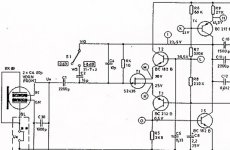
Here is mine; I also eliminated Cgd by a feedback, also the feedback was used to equalize peak around 9.5 KHz. later I replaced 33 nF cap with a serial LC contour. Cmiller was greatly reduced by loading it on a P-N junction of a BJT. I always simplify equations before solving them so part count is always minimal as possible for the end result:

My point was; no need to worry about noises of 2SK170 in a power amp on 10 mA current if it works well on less than 1 mA with huge resistance of input signal source, that's all. I don't know why John was so nervous since I actually added a water on his mill.
scott wurcer said:
How true.
Anatoliy, here's part of a schematic from 30yr ago of the classic Neumann U89 showing the technique of putting feedback around the capsule eliminating the Cgd from the gain equation (still figures in the noise a little TANSTAAFL).
Hello Scott
I am bit confused the feedback goes around T1 is that what you mean , how is the capsule enclosed by the feedback .
Regards
Arthur
PHEONIX said:
Hello Scott
I am bit confused the feedback goes around T1 is that what you mean , how is the capsule enclosed by the feedback .
Regards
Arthur
Parallel feedback, so feedback load dominate. In my case a feedback is in series, so frequency range is wider on lows. However, for closed miking U89 is better because it is more immune against pops, but in my case it is not necessary: I did not design microphones for taking in mouthes.
T3,T5, and T4 form a very high gain amplifier (T2 is just a cascode). It is then a capacitive feedback circuit where the gain is the capsule capacitance divided by the feedback capacitance (note gain switch). The FET gate becomes the inverting input and virtual ground, etc. I don't really want to get JC going again on the subject. I and a couple of friends have built several with 2 sk170's and a low power op-amp they work great.
- Status
- Not open for further replies.
- Home
- Amplifiers
- Solid State
- John Curl's Blowtorch preamplifier