Re: Re: Re: Btw-2
I said : "provided that it's 100% common mode and 0% differential"
Apparently, this piece of BS has also more or less a differential effect. Therefore it works a bit.
>checked this by yourself? Come on, do you really think I'm gonna wasting my time on this?
Anyhow, I insist that you cannot correct the offset without interfering with the signal path, period.
PS: I'm far from polite as you know and I detest PC.
syn08 said:Always polite and considerate as usual...
Have you checked this by yourself? Because guess what, it works! Why, we may discuss 😀
I said : "provided that it's 100% common mode and 0% differential"
Apparently, this piece of BS has also more or less a differential effect. Therefore it works a bit.
>checked this by yourself? Come on, do you really think I'm gonna wasting my time on this?
Anyhow, I insist that you cannot correct the offset without interfering with the signal path, period.
PS: I'm far from polite as you know and I detest PC.
scott wurcer said:
Guys,
A question, why do you parameterize around beta? I would do it around Idss. In an ideal model beta is pretty much constant. If you take
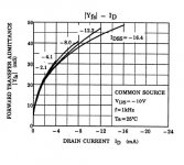
Toshiba's plot from the 2SK170 datasheet at 1mA (for instance) just about any part you grab will have 15mS gm ie. constant beta. I know the graph does not fit that well to the square root function on these short channel devices but I consider that a second order effect.
Like so...
vto = -sqrt($IDSS/whatever),beta = whatever
Scott,
Reason is: Idss also depends on Vds through Lambda which is a separate model parameter as Idss=Idss0*(1+Lambda*Vds)
Beta is a constant depending on the channel geometry and the carriers mobility. It is the channel geometry (that is, the length) that gives the Beta (and therefore Idss) dispersion.
Therefore, by parametrizing Beta, you model the dispersion of the manufacturing process (litography) which is, in particular for such short channel devices, in fact, correct. The other apparently correct option is to parametrize Vto but Vto essentialy depends on the impurity concentration in the substrate, which is technologically not really a variable.
Your equation holds only if Lambda=0 which is in general a very rough approximation.
Re: Re: Re: Re: Btw-2
Ok, much better, so it "somehow" works 😀 😀 😀
Perhaps because it source/sinks current in a virtual ground node, adjusting the diff pair biases, so that the output settles to zero? And perhaps the output impedance of the servo has no AC impact as it would, if it would be connected to the inverting input?
P.S. PC has nothing to do with politeness and consideration. But if you enjoy being rude to anybody that does not share your views, then so be it. I'm not here to poop your party.
Edmond Stuart said:
I said : "provided that it's 100% common mode and 0% differential"
Apparently, this piece of BS has also more or less a differential effect. Therefore it works a bit.
>checked this by yourself? Come on, do you really think I'm gonna wasting my time on this?
Anyhow, I insist that you cannot correct the offset without interfering with the signal path, period.
PS: I'm far from polite as you know and I detest PC.
Ok, much better, so it "somehow" works 😀 😀 😀
Perhaps because it source/sinks current in a virtual ground node, adjusting the diff pair biases, so that the output settles to zero? And perhaps the output impedance of the servo has no AC impact as it would, if it would be connected to the inverting input?
P.S. PC has nothing to do with politeness and consideration. But if you enjoy being rude to anybody that does not share your views, then so be it. I'm not here to poop your party.
I would really like to speak my mind about some design efforts, but I am not allowed, and besides, it is not helpful. Actually, Lineup, while you made a design for exactly the wrong reasons, I can see that it could work, sort of.
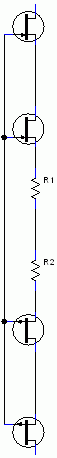
Of course, we use a similar circuit for balanced output designs. You will find it in the JC-80, Blowtorch and the Parasound JC-2. We need it to get the common mode combined output to be close to ground. It does attempt to make the output offset close to zero, but is it the easiest way to do this with a single ended output?
Of course, we use a similar circuit for balanced output designs. You will find it in the JC-80, Blowtorch and the Parasound JC-2. We need it to get the common mode combined output to be close to ground. It does attempt to make the output offset close to zero, but is it the easiest way to do this with a single ended output?
Re: Re: Re: Re: Re: Btw-2
One more thing: Do yourself a favor and forget that 'servo'. Discussing it further might harm your reputation,
NO! NOT better now. It works a bit by accident. The reasoning behind the concept is completely crooked. The person who invented this waster clearly demonstrates a serious lack of knowledge about electronics design. Why? Please read my previous posts.syn08 said:Ok, much better, so it "somehow" works 😀 😀 😀
[snip]
One more thing: Do yourself a favor and forget that 'servo'. Discussing it further might harm your reputation,
I get THD20k = 10 ppm at 1Vrms output voltage and 0,003% at 3 Vrms output voltage running 8mA through the JFETs.
Using MicroCap.
Your sims are thus (about) the same as mine.
Sigurd
Using MicroCap.
Your sims are thus (about) the same as mine.
Sigurd
Edmond Stuart said:Thanks. What are your THD figures?
john curl said:I would really like to speak my mind about some design efforts, but I am not allowed............
Afraid of a sinbin? So what! Tell us what you really think.
Cheers,
E.
Re: Re: Re: Re: Re: Re: Btw-2
Let's drop it, I don't want this to go into another mud sling. Anybody that wants to simulate or experiment with can give it a shot and make his own opinion.
You are back on my **** list and I suggest you do the same.
Edmond Stuart said:
NO! NOT better now. It works a bit by accident.
Let's drop it, I don't want this to go into another mud sling. Anybody that wants to simulate or experiment with can give it a shot and make his own opinion.
You are back on my **** list and I suggest you do the same.
Why connect the gates together instead of having the upper n-FET/lower p-FET gates connected to the corresponding sources?
SY said:Why connect the gates together instead of having the upper n-FET/lower p-FET gates connected to the corresponding sources?
Less parts count, though different Vgs JFETs are needed, also PSRR is much better: Lineup is worried about it a lot.
One more version: to bootstrap them from outputs, but I prefer feed-forward approach.
Re: Re: Don't buy it!
Did it corrobate with listening tests?
With all respect that are only simulationsPMA said:You said that only even harmonics are cancelled. I am not speculating, or chating. You can visit my web page and compare distortion of a simple JFET differential pair to a complementary differential pair.
Did it corrobate with listening tests?
syn08 said:
Scott,
Reason is: Idss also depends on Vds through Lambda which is a separate model parameter as Idss=Idss0*(1+Lambda*Vds)
Beta is a constant depending on the channel geometry and the carriers mobility. It is the channel geometry (that is, the length) that gives the Beta (and therefore Idss) dispersion.
Therefore, by parametrizing Beta, you model the dispersion of the manufacturing process (litography) which is, in particular for such short channel devices, in fact, correct. The other apparently correct option is to parametrize Vto but Vto essentialy depends on the impurity concentration in the substrate, which is technologically not really a variable.
Your equation holds only if Lambda=0 which is in general a very rough approximation.
We denigrate FETs so the type 1 models are the default here, but still what am I missing? From the graph gm = sqrt(2*beta*Id) within the thickness of the line at 1mA is 15mS for the entire Idss range i.e. beta is the same. This is what, practically, I find when putting a 2SK170 into my Quantec and reading the gm they are approximately all the same after trimming Vgs for 1mA.
More tomorrow, I'm away from my primary references where I have a tedious derivation of beta from all the process parameters.
I have a great quote from Van der Ziel where he calls a derivation "tedious but trivial".
Re: Re: Re: Re: Re: Re: Re: Btw-2
Here we go again. Running out of arguments? Not listening to my arguments?
Anyhow, it's a waste of time to simulate something that violates sound design principles.
BTW, what about putting YAP on the **** list too?
syn08 said:Let's drop it, I don't want this to go into another mud sling. Anybody that wants to simulate or experiment with can give it a shot and make his own opinion.
You are back on my **** list and I suggest you do the same.
Here we go again. Running out of arguments? Not listening to my arguments?
Anyhow, it's a waste of time to simulate something that violates sound design principles.
BTW, what about putting YAP on the **** list too?
lineup said:
the problem with constant current + constant voltage
is always = no gain.
Excercise for you: how to calculate a power gain when you know input and output impedances, and a voltage gain is equal to 1?
scott wurcer said:
We denigrate FETs so the type 1 models are the default here, but still what am I missing? From the graph gm = sqrt(2*beta*Id) within the thickness of the line at 1mA is 15mS for the entire Idss range i.e. beta is the same. This is what, practically, I find when putting a 2SK170 into my Quantec and reading the gm they are approximately all the same after trimming Vgs for 1mA.
More tomorrow, I'm away from my primary references where I have a tedious derivation of beta from all the process parameters.
I have a great quote from Van der Ziel where he calls a derivation "tedious but trivial".
Scott,
You are not missing anything; if you look at the models I posted, 2sk170 has Lambda=1.923m while 2sj74 has Lambda=4.464m. This would make (at Vds=10V) a 1.9% error in Idss for the 2SK170 and 4.4% for 2SJ74 The larger error for the P channel is obvious in the picture below. Compare with the 2SK170 gm you posted...
Sometimes the error could be small, but I think it's good practice to a) follow physics/logic behind the parameters b) keep parameters as much as possible generic and decoupled. I agree that parametrizing Idss makes much more sense from a circuit perspective but it's not neccessary the most correct/precise method.
Attachments
Actually, I don't like working as low as 1ma, because much of the potential of the jfet is compromised. It is both noisier and lower gm than it would be with higher currents. Also, one of the big advantages of jfets is that they CAN operate at higher current without getting too much current noise. This is very important with power amps, because you can more easily and effortlessly drive the second stage when you have more input idle current.
john curl said:Actually, I don't like working as low as 1ma, because much of the potential of the jfet is compromised. It is both noisier and lower gm than it would be with higher currents. Also, one of the big advantages of jfets is that they CAN operate at higher current without getting too much current noise. This is very important with power amps, because you can more easily and effortlessly drive the second stage when you have more input idle current.
Actually at low currents FETs beat bipolars for noise. In microphones running FETs at 1mA or even 500uA or less is a normal situation. In part it's just different applications, I would not run at 10V Vds due to impact ionization.
Scott,
Are you referring to JFETs generically or just the 2SK170 / 2SJ74 and the like ? I remember vakely that some JFETs do have very poor noise specs, especially at low current ......
And would you be recommending against Vds above 10V in all applications or just when using low current bias ?
Thanks,
Patrick
- Status
- Not open for further replies.
- Home
- Amplifiers
- Solid State
- John Curl's Blowtorch preamplifier