KBK said:....
Anything else, is just people polluting the thread with their lack of depth of knowledge of the top of the field of audiophile design, mixed in with their psychological issues and insecurities......So we do what we can, (And I do fully realize that it sounds insulting-but it is an apt simile) but it's more than a bit like having one's arms bit to pieces by a pup one is trying to bandage.....
Too much for disrepfectful contempt towards "not enlightened" designers.
Being as it stands, high end audio is much more a dark ages cult for the initiated than a serious endeavour for advancement in sound reproduction.
They should not forget audio exists in the first place, because generations of earlier scientists opted for a much more serious approach, from which technology became available be put to use.
As long as terms like "fields" and so on are casually sprinkled as basis for argument, then this will keep being as it is at least for me.
An endless chain of fun, with preciously scarce valuable insights.
Rodolfo
PD This does not imply disregard of the fact our hearing is a still not fully understood process, extremely sensitive, and that current technology is unfortunatelly quite close to thresholds of detection. Were there an order of magnitude or better of difference, there should be no discussion.
hermanv said:Capacitors for example have a number of second order flaws such as dielectric absorption, series resistance, series inductance, voltage induced deformation, microphonic effects, leakage resistance and probably a couple I didn't think of.
Even the guys I know who design switching power supplies recognize these flaws. In their case, the flaws affect the power supply efficiency and generated EMI which are real and measurable concerns for them.
But that brings up a good point.
About 97.32% of the DIY and otherwise audiophile crowd do not believe that power supply filter caps are "in" the audio signal path for most amplifier and preamplifier designs. They must not believe in nodal circuit analysis. The following comment is not intended for the people who think this way.
Given the capacitor flaws described by hermanv, why aren't more people concerned about the power supply filter cap? It seems to me that with a capacitor input power supply filter, 120 times every second (or 100 in a large part of the world) the input capacitor gets pulsed by the diodes for a short period. These pulses are often Amperes of current, depending on the value of capacitor and the supplied current. In the usual amplifier configuration, the signal path for the audio signal passes directly through the very same imperfect circuit element that is being stressed by these current pulses. Wouldn't you consider this a limitation in these designs?
It seems to me that a good part of the success of the Blowtorch (remember the Blowtorch?) is what takes place in the big aluminum box that doesn't have any knobs on it.
Of course, that's presuming that you believe that the Blowtorch is a successful design. (Side question: I wonder what the correlation is between those who think the Blowtorch is a successful design and those who don't think that a power supply filter cap is in the audio signal path.)
... It seems to me that with a capacitor input power supply filter, 120 times every second (or 100 in a large part of the world) the input capacitor gets pulsed by the diodes for a short period. These pulses are often Amperes of current, ...
Which is why a choke input power supply may be a good idea for a SOA preamp? I have never heard of a direct comparison to a capacitor input filter, especially a comparison with "all other things being equal", but some claim they do sound better.
Choke input is idealistic, but problematic. It is difficult to keep it from getting out of control. It would be best with tubes, but pi filters with a cap, inductor, cap can be very stable, and better than a single cap input.
NPO and non-piezo ceramic may be better than soft teflon, I believe...
Or teflon with ceramic in parallel, to cover all audio band, in a heavy stiff hermetical body.
Or teflon with ceramic in parallel, to cover all audio band, in a heavy stiff hermetical body.
While you are correct about the bulk storage capacitor most low level circuits (i.e Blowtorch et al) follow this cap with a regulator and second cap. The 120Hz pulses are significantly attenuated in the second cap. Still you are correct that a nodal model places the entire storage/regulator/filter as a 3 or 4 pin node capsule in series with the load.CG said:...edit...
Given the capacitor flaws described by hermanv, why aren't more people concerned about the power supply filter cap? It seems to me that with a capacitor input power supply filter, 120 times every second (or 100 in a large part of the world) the input capacitor gets pulsed by the diodes for a short period. These pulses are often Amperes of current, depending on the value of capacitor and the supplied current. In the usual amplifier configuration, the signal path for the audio signal passes directly through the very same imperfect circuit element that is being stressed by these current pulses. Wouldn't you consider this a limitation in these designs?
...edit...
I believe John said earlier that he likes combination series and shunt regulation, this allows nearly independent modeling of Z vs. frequency. If I designed power amps, I think I'd lean toward a capacitor multiplier scheme just to reduce those high current pulses on the final cap.
I too like polystyrene caps, my older and less reliable memory had them priced them higher than Teflon especially in the multiple microfarad sizes. I would sure like to hear the copper and film caps, I'm just not willing to sell the house for the privilege. One last note, my listening says that the multicap (i.e. multiple foil contact lands paralleled) design offers a real improvement.
john curl said:Choke input is idealistic, but problematic. It is difficult to keep it from getting out of control. It would be best with tubes, but pi filters with a cap, inductor, cap can be very stable, and better than a single cap input.
Using a 4.7uF to 10uF quality film cap before the choke, stabilizes the system, and it is still 95% choke input.
Using the same reasoning and the same type of nodal analysis, it can be shown that that there is a common mode connection through the AC mains system 100 or 120 times a second between all the audio equipment located on the same mains spur.
Keep in mind that this common mode signal connection is modulated by the waveform of each unit's power supply characteristics. In the case of a Class AB power amplifier, the current draw changes with the musical content of what is played, so the waveform for that piece of equipment is constantly varying in some kind of relation to the music. This adds an additional time varying modulation component to the common mode connection.
You can even measure this with a moderately wideband oscilloscope current probe clamped over a line cord and a battery powered oscilloscope. (Maybe an AC powered scope would also work for this and give useful measurements, but I've never tried that.)
Just think about the entire system here. What determines the common mode rejection of the various pieces in an audio system? There's the components in the power supply of each. Some kinds of transformers have lower capacitance between primary and secondary. You can also occasionally find various chokes in the circuit. There's even the mains cabling. On the amplification side, fully balanced circuitry can reject common mode signals. Opamp style amplifiers can as well, presuming that the impedances "seen" by the two nominal inputs are the same. That's not the case very often - what's a volume control do to this? Or the output impedance of a preamp (for example) added to the input components build into the power amplifier?
Many of these common mode signal frequencies can be well above the audio range - remember the waveform of the diode conduction period. So they don't matter, you say? Just because you can't hear these frequencies directly, when they combine inside your audio system in one of the boxes, the signal frequencies can mix down into the audio bandwidth easily enough. Those you can hear, and like jitter caused tones in a digital audio system, these tones are not harmonically related to the music signal. We're not talking about THD here.
The coolest part is that none of this is ever measured. Well, maybe not never, but as far as I can tell at least not very often. This is a system problem. How many times have you actually ever seen common mode rejection specs or measurements for a piece of audio equipment? Or power supply rejection, both differential and common mode? Or reflected power supply noise? I wonder how many even consciously consider any of this. But, there's scientific analysis of this in places like Ott's book on noise. Not specifically aimed at musical reproduction systems, however.
Just why do some people swear by audio coupling transformers? Or the use of "balanced power" in the AC supply system?
Man, it's only the beginning of September and I've already used my allotment of bandwidth here...
We must use a 100MHz scope to be good for 10MHz square waves, don't we? So why how passing signals 10 times 20kHz can't be important in an audio amp? I thought that was absorbed many decades ago. Plus all the spuriae, intermodulations, and common mode PSU mixing.
CG said:(...) Just think about the entire system here. What determines the common mode rejection of the various pieces in an audio system? (...)
Not sure if you're aware of this paper or not, but there's a nifty article, first pointed out to me by jcx, called "A General Relationship Between Amplifier Parameters And Its Application To PSRR Improvement" by Sackinger, Goette and Guggenbuhl. This used to be available on the web, but I can't find it there now. I do have a copy, so if anybody would like one, just shoot me an email.
Some people will not like this idea I know, but I think the presence of 120 Hz PSU ripple is one argument for having the open-loop bandwidth of a power amp be less than 120 Hz (assuming the GBW is held constant of course). I'll be quiet now 🙂.
Thanks for the paper andy. Then I found my own previously saved copy. What is the old saying about forgetting more than you learn?
The Sackinger et al paper is certainly interesting. If we allow for a generalization from the monolithic CMOS operational amplifiers to the discrete circuits discussed (occasionally, above) then it appears that simple single differential stage amplifier designs have a limit where the CMRR and PSRR cannot be individually improved without worsening the other.
Acm(s) + Add(s) + ***(s) = 1 from equation 3 of the paper.
To me, this suggests maximizing the CMRR and then attending very carefully to the PSU design to compensate for the poor PSRR.
Cascoding the input stage is shown to break the relationship when using a fixed reference for the cascode. I wonder if a bootstrapped cascode would show better/worse performance in this regard?
The best performance in the paper comes from expanding the opamp to a differential output (sound familiar Blowtorch fans?) and then regulating the common mode output voltage against an external reference voltage using a differential difference amplifier to sense the two differential output lines.
I have not done a prior art search, but I recall something very similar (in concept, at least) proposed by Richard Marsh where he used a an opamp to regulate the common-mode output voltage of a split rail power supply using ground as the reference. In one case, the "op-amp" was one channel of a stereo power amplifier.
I have used this circuit topology myself to good effect when the chosen opamp was optimised for CMRR but showed poor PSRR.
VivaVee said:Cascoding the input stage is shown to break the relationship when using a fixed reference for the cascode. I wonder if a bootstrapped cascode would show better/worse performance in this regard?
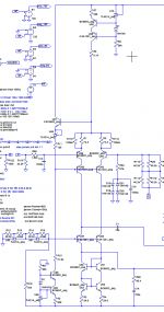
Yes, cascoding the input stage breaks that relationship, but only if you move the input side of the compensation cap to the emitter of the cascoding transistor (also described by Self in his book, which references Sackinger et al). If you combine that technique with bootstrapped cascoding of the input stage, then at least according to simulation, the PSRR becomes extremely high. I'm in the process of doing a layout of an amp front end that does just that. One caveat is that compensation of the local loop gain of the VAS is needed - a series RC from the base of the CE amp of the VAS to its corresponding power supply seems to do the trick.
I've attached a partial schematic below. Compensation cap C1 goes to the collector of the VAS while the lower signal goes the the VAS base. The series RC is for compensation of the local VAS loop.
Attachments
CG said:[snip]Given the capacitor flaws described by hermanv, why aren't more people concerned about the power supply filter cap? It seems to me that with a capacitor input power supply filter, 120 times every second (or 100 in a large part of the world) the input capacitor gets pulsed by the diodes for a short period. These pulses are often Amperes of current, depending on the value of capacitor and the supplied current. In the usual amplifier configuration, the signal path for the audio signal passes directly through the very same imperfect circuit element that is being stressed by these current pulses. Wouldn't you consider this a limitation in these designs?[snip]
Yers of course the power supply capacitor, and the house mains panel, are 'in the loop'. So?
Let's use a thought experiment: I have this amp that produces an output current into a load. Now, I know that this load current also flows through the power supply cap. So, that impacts the voltage across the power supply cap. That means that part of that load current turns up as 'ripple' voltage across the cap, and, across the amp supply line.
Of course, there's a lot more junk on that supply line, like 50/60Hz mains and its harmonics, noise from the neighbour's electrical lawn mower, you name it. A competent design is one that makes sure that all of that junk has such a low impact on the output signal that it doesn't lead to audible degradation. PSRR versus frequency comes to mind. You can take care of it in the amp, in the supply, by specifying the best supply caps you can afford, sensible layout, etc.
So, it is a mystery for me why again and again someone brings up: 'but the supply caps are also in the signal path' and then, silence. As if he/she wants to imply: 'now your world falls apart'. Well, no, not yet.
Jan Didden
janneman said:Let's use a thought experiment: I have this amp that produces an output current into a load. Now, I know that this load current also flows through the power supply cap. So, that impacts the voltage across the power supply cap. That means that part of that load current turns up as 'ripple' voltage across the cap, and, across the amp supply line.
Please extend this same thought experiment to the power supply current that flows through the load.
CG said:
Please extend this same thought experiment to the power supply current that flows through the load.
Ehhh, as far as I can see, the power supply current going through the load is the same as the current I mentioned in my post.
There is some additional power supply current going through the pre- and driverstages of the amp, and depending whether those stages are in class A, B or AB, some of that also goes through the load. But the power supply current that ends up in the load is the load currrent, no? Am I missing something?
For an amp with infinite PSRR, the power supply voltage has no influence on the load voltage or current. In real amps, there is an influence, because, as I mentioned, the load current through the ps caps leads to signal-correlated ps ripple. It's a matter of straight-forward engineering to make sure that that influence is an arbitrarily level below the signal, limited basically by how much money and time you want to spend on it.
Jan Didden
- Status
- Not open for further replies.
- Home
- Amplifiers
- Solid State
- John Curl's Blowtorch preamplifier