chest
A good question Glen.
The whole problem with this thread is that it is conducted by someone who keeps his cards close to his chest. I have no doubt that he has good reasons to do so, but the consequences of such policy are evident. So nobody should be amazed that the quality of this thread is far from optimal.
Cheers,
Edmond.
G.Kleinschmidt said:
So why on earth was it made a sticky?
A good question Glen.
The whole problem with this thread is that it is conducted by someone who keeps his cards close to his chest. I have no doubt that he has good reasons to do so, but the consequences of such policy are evident. So nobody should be amazed that the quality of this thread is far from optimal.
Cheers,
Edmond.
John Curl is probably the only one from whom I have learnt something in this forum. It depends if you can read in his posts, or not.
Re: chest
It's more the various agendas of those with a marketing concern in audio that are a source of rot. This thread isn’t unique in that regard.
Cheers,
Glen
Edmond Stuart said:
A good question Glen.
The whole problem with this thread is that it is conducted by someone who keeps his cards close to his chest. I have no doubt that he has good reasons to do so, but the consequences of such policy are evident. So nobody should be amazed that the quality of this thread is far from optimal.
Cheers,
Edmond.
It's more the various agendas of those with a marketing concern in audio that are a source of rot. This thread isn’t unique in that regard.
Cheers,
Glen
It has nothing to do with relevance, it's how people act here, and then come crying to the moderators when their own ox is gored.
I think stories John tells are of historical interest and gave some insight as to how it would be to work with him, for example. Its just that if he does this, he can't complain about others going off topic-unless the topic of the thread were John Curl's History of Solid State Circuits. If he started such a thread, he could lay out his accomplishments in a coherent manner for posterity as I doubt there would be too much argument, and if irrelevent comments were made, the would be deleted, as they would be off topic. He could also start a thread about Open Loop Design Topologies and limit it to that subject.
Instead he seems to prefer to hang out here with his buddy Glenn and shoot the bull..
Hello Bob,
telescopic cascode seems to be the standard name for what I showed in the PDF (attached again). I have seen that in many places. I like the name, and it also makes it easy to separate telescopic cascode from folded cascode.
Driven, on the other hand, was a new word to me until I read Walt Jung's comment in the Baxandall thread. I have used it, but not had a good name for it. DTC = Driven Telescopic Cascode
🙂
To me a DTC is when one locks Vds (for a FET) between drain and source, which is what we want to actually do as we want to have a fixed Vds for the FET. Often, a cascode is connected to GND which will not lock Vds to an exact fixed voltage.
Your way of using the output voltage to create a voltage for a DTC
is new to me.
Sigurd
Bob Cordell said:
Hi Sigurd,
I have not heard the term "telescopic" cascode before, but I have used the term "driven cascode" to mean what I think is the same thing: namely, the bases (or gates) of the cascode are driven with a signal that is a reasonable replica of the common-mode signal applied to the differential pair being cascoded.
I have had very good results in non-inverting power amplifiers by driving the bases of the cascode stage with a replica of the common mode signal derived directly from the output of the amplifier with a divider network that is substantially identical to the feedback network. This yields a very close replica of the actual common mode signal to which the diff pair is subjected without adding and circuitry that might load the input circuits.
The underlying assumption here, of course, is that the differential error input to the LTP being cascoded is small by comparison. In the case of a no-NFB amplifier, this would likely be not true.
Cheers,
Bob
Attachments
PMA, I think that you have it right. Not everyone is equipped to understand what we talk about on this thread when we are really communicating. They just don't have the prerequisites for it. There is nothing wrong with this, as I would have a lot of trouble sitting in an advanced math class, or even a graduate level class in quantum mechanics. I just don't have the prerequisite courses or knowledge within me to hardly understand what is going on in almost any advanced class of anything.
However, I would just avoid the course and the lecture, or I would seriously attempt to learn what is necessary to understand the subject further.
There are several electronic engineers here who can easily understand what PMA and I know, but they just don't happen to believe that it is important to audio quality. They are usually more productive on alternate threads to this one. I don't begrudge them, I just don't read them very often, and I wish that they would treat me with the same courtesy.
Sigurd Ruschkow said:.............
To me a DTC is when one locks Vds (for a FET) between drain and source, which is what we want to actually do as we want to have a fixed Vds for the FET. Often, a cascode is connected to GND which will not lock Vds to an exact fixed voltage..............
Hi Sigurd,
I'm not sure if you are aware of an important aspect of the circuits around Vout3 and Vou6. The crux is that the gate (or base) current is fed back. In this way the output impedance is further increased and the Early effect almost completely eliminated. It's called a Hawksford cascode. But there are caveats. See also: http://www.diyaudio.com/forums/showthread.php?postid=293597#post293597
Cheers,
Edmond.
edit: I've corrected the erroneous link.
Hello Edmond,
good observation! Yes, the gate current in the circuits with Vout 3 and Vout6, which shows driven telescopic cascodes using JFETs as the cascode element, will go back to the source of the main transistor (SK170). About 30 nA.
In the link you posted, people get oscillations, but I do not see that in my sims. I do get a small peek at about 15MHz, but that is easily taken care of (if needed or wanted) with a smallish cap. Maybe not even needed when the design is put on a PCB as the parasitic capacitances will probably fix this.
I have seen no problems with the circuit with Vout6, for ex.
Regards,
Sigurd
Edmond Stuart said:
Hi Sigurd,
I'm not sure if you are aware of an important aspect of the circuits around Vout3 and Vou6. The crux is that the gate (or base) current is fed back. In this way the output impedance is further increased and the Early effect almost completely eliminated. It's called a Hawksford cascode. But there are caveats. See also: http://www.diyaudio.com/forums/showthread.php?postid=293597#post293597
Cheers,
Edmond.
edit: I've corrected the erroneous link.
PMA, what I would really like to see is a simulation of the previous full 4 quadrant folded cascode that you did before, except that the 4 bias resistors would be 10 ohms, rather than 51 ohms or so. This would give me a baseline, so to speak. If you are too busy now, I understand. The second circuit of interest to me is just the usual complementary transistor output stage with emitter resistors and the bias/resistor ratio set for lowest 7th harmonic when in class AB transistion. As we know, Barney Oliver did a very good overall THD minimization back in the early 70's, BUT he did not minimize higher order, just total THD. I wish that I could do these easily, but I am still limping along, trying to learn how to do it on a PC.
PMA, I think you are going to give Charles and me a good run in the audio 'horse race' that we compete in, in future, if not already.
PMA, I think you are going to give Charles and me a good run in the audio 'horse race' that we compete in, in future, if not already.
John,
as PMA is busy now,
if you wish, I can try do do the simulations. I use the same software as PMA, and even though I am probably not as good as PMA doing sims, I am willing to give it a try. I have the time.
If you hand me the schematics, be it links or handmade schematics, I will start asap.
Sigurd
as PMA is busy now,
if you wish, I can try do do the simulations. I use the same software as PMA, and even though I am probably not as good as PMA doing sims, I am willing to give it a try. I have the time.
If you hand me the schematics, be it links or handmade schematics, I will start asap.
Sigurd
john curl said:PMA, what I would really like to see is a simulation of the previous full 4 quadrant folded cascode that you did before, except that the 4 bias resistors would be 10 ohms, rather than 51 ohms or so. This would give me a baseline, so to speak. If you are too busy now, I understand. The second circuit of interest to me is just the usual complementary transistor output stage with emitter resistors and the bias/resistor ratio set for lowest 7th harmonic when in class AB transistion. As we know, Barney Oliver did a very good overall THD minimization back in the early 70's, BUT he did not minimize higher order, just total THD. I wish that I could do these easily, but I am still limping along, trying to learn how to do it on a PC.
PMA, I think you are going to give Charles and me a good run in the audio 'horse race' that we compete in, in future, if not already.
transparent ingenuity.Sigurd Ruschkow said:If you hand me the schematics, be it links or handmade schematics, I will start asap.
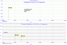
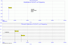
Hi John, I assume you might be interested what happens if I change my complementary-differential low-feedback topology into simple-differential.
The preamp is dicussed in a thread named "New Dispre ....."
The 1st image is for complementary-differential, as designed:
The preamp is dicussed in a thread named "New Dispre ....."
The 1st image is for complementary-differential, as designed:
Attachments
Sigurd, there is no real secret here, as most of the toplogies are already on this thread somewhere. Let's see what PMA can do first, since he put up the topologies and has them handy. You could always go to his website and get them, if you wish.
PMA said:Hi John, I assume you might be interested what happens if I change my complementary-differential low-feedback topology into simple-differential.
The preamp is dicussed in a thread named "New Dispre ....."
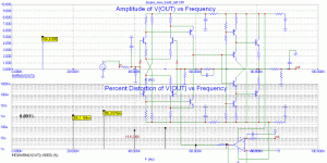
What if you keep the complementary-differential topology, but change the devices to germaniums? Do you have any SPICE models of some complementary Ge devices?
se
john curl said:Interesting PMA, now try to push both 5 to 10 times harder and compare.
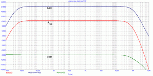
5 times. Always into 600 ohm. Complementary-differential:
Attachments

- Status
- Not open for further replies.
- Home
- Amplifiers
- Solid State
- John Curl's Blowtorch preamplifier