Well said KBK, but I must admit that I had some difficulty following you completely, and I suspect others will also.
For more info on the 'Ragtime Razzmatazz' Vol 2: " ... Seven microphone pickup pattern combinations were tested, but only one finally succeeded in satisfying our sonic goal. That goal was to create a precise and living portrayal of the sound field of the instrument, integrated into the warm acoustics of its natural setting. Two of the superb Schoeps CMC-3 condenser microphnes with omni capsules were the overwhelming choice --- and together with minimal signal processing, plus high quality mastering, matrixing and disc presssing, result in the fine technical qualities of this record. Final evaluation of the master tape was performed using the Wilson Audio Modular Monitor (WAMM) system. Mastered by: Bruce Leek, Matrix by: Rick Goldman ".
It is unfortunate that many have no idea why we even bothered to make independent recordings, but they were necessary to evaluate our own equipment.
Thanks, Sy, for checking this!
10mV is a voltage that not many sources should output. Still, for a commercial product, I would put a cap in front of the transformer
so the customer will never ever experience transformer failure due to excess offset voltage.
To me, this is a major drawback for transformer coupled audio gear.
Luckily, using a LL1670 transformer in a I/V conversion circuit with the PCM1794/2, the mid-rails-DC-ofsets cancels out to zero.
SIgurd
SY said:
10mV doesn't saturate a JT-11P1 (I just checked it).
I can't find any sources in-house (2 CD players, a DVD player, a direct-coupled phono stage) that have that much offset, and I don't think my zoo is atypical.
One of the points is that the mass considerations -complex dynamic LCR of the given signal itself, combined with the pathways it must navigate-this is the parts themselves- will vary..as stated, dynamically. So the small signal leading and lagging character of a given transient vs that of a large signal leading and lagging character of a transient..and how the two intermix, on all potential levels -is a critical point. Transformers -seem- to do that better than -most- transistor circuits.
Meaning, that (like anything) under the right circumstances of use... they maintain their micro-macro 'balance' under complex varying loads, ie real life use...better than most active circuits.
A way to see it is, how do you dump the ball into the hoop, when standing on a chair and can touch the hoop directly, as you are that close? How do you dump the ball when you are in mid air, with a 90 degree twist? How do you dump the ball when flying through the air and smashing into a guard when 2 feet from the hoop? How do you dump the ball when at the free throw line? How do you dump the ball when at the other end of the court in the last two seconds of the game?
Your answer had BETTER BE..exactly the same way, each and every freaking time. Same angle, same speed, same spin, same launch, etc. All identical.
If you can't get or aren't trying to get transient and or micro-transients to do the same or aren't considering these points when designing audio gear - you are entirely missing the point. Some might say such is obvious..but it obviously isn't. There's lots of bad gear out there, even at the high end of things. It comes down to a lack of connectivity to what it takes to get a circuit or part in place that does these things, or knowing the factors or points that allow such good handling of a signal to come about.
But most specifically how this pertains to how the ear hears-and how we measure electrical circuits. And then again, how the given individual listens. It can even come down to being stated as a personal awareness issue-that the given personal position and awareness allows some specific insights on how to get these things done with circuitry.
Good try, KBK, but I think you must do an even simpler explanation for others to understand you.

KBK -
not sure if I understand you exactly, but maybe you have some form of math that can explain what you are saying?
Sigurd
not sure if I understand you exactly, but maybe you have some form of math that can explain what you are saying?
Sigurd
KBK said:One of the points is that the mass considerations -complex dynamic LCR of the given signal itself, combined with the pathways it must navigate-this is the parts themselves- will vary..as stated, dynamically. So the small signal leading and lagging character of a given transient vs that of a large signal leading and lagging character of a transient..and how the two intermix, on all potential levels -is a critical point. Transformers -seem- to do that better than -most- transistor circuits.
Meaning, that (like anything) under the right circumstances of use... they maintain their micro-macro 'balance' under complex varying loads, ie real life use...better than most active circuits.
A way to see it is, how do you dump the ball into the hoop, when standing on a chair and can touch the hoop directly, as you are that close? How do you dump the ball when you are in mid air, with a 90 degree twist? How do you dump the ball when flying through the air and smashing into a guard when 2 feet from the hoop? How do you dump the ball when at the free throw line? How do you dump the ball when at the other end of the court in the last two seconds of the game?
Your answer had BETTER BE..exactly the same way, each and every freaking time. Same angle, same speed, same spin, same launch, etc. All identical.
If you can't get or aren't trying to get transient and or micro-transients to do the same or aren't considering these points when designing audio gear - you are entirely missing the point. Some might say such is obvious..but it obviously isn't. There's lots of bad gear out there, even at the high end of things. It comes down to a lack of connectivity to what it takes to get a circuit or part in place that does these things, or knowing the factors or points that allow such good handling of a signal to come about.
But most specifically how this pertains to how the ear hears-and how we measure electrical circuits. And then again, how the given individual listens. It can even come down to being stated as a personal awareness issue-that the given personal position and awareness allows some specific insights on how to get these things done with circuitry.
Sigurd, I see your point, but the question is, what are the sources of offset and how is the offset affected by a 1k (or so) DC load.
And I'll confess to being incomplete in my offset check- I just used a triangle wave from my function generator to see saturation, which I couldn't. But your point is well-taken, I really should take a spectrum.
And I'll confess to being incomplete in my offset check- I just used a triangle wave from my function generator to see saturation, which I couldn't. But your point is well-taken, I really should take a spectrum.
PMA, it is true that you did not extend your measurement to include 7th harmonic, but I suspect that it is not there. Now why do I think this? Well, a class A system has a difficult time generating any significant 7th harmonic distortion.
This is NOT true with IC op amps, like the ones that Scott designs, that are almost always starved in the output stage current and therefore CAN generate measurable 7th harmonic under real world conditions. This is what I am concerned about, even today.
This is NOT true with IC op amps, like the ones that Scott designs, that are almost always starved in the output stage current and therefore CAN generate measurable 7th harmonic under real world conditions. This is what I am concerned about, even today.
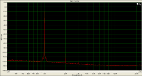
Yes, I have not extended it in THIS image. You know, professional wideband spectrum analyzer like the one used, Agilent, quickly looses dynamic range for extended frequency range in just 1 measurement. But I did check higher frequencies.
This is a discrete, very low FB, class A output audio design. I tested it at 100kHz and 50 ohm load - pretty severe. At the same time, I tested 2 amps with pretty good VGA opamps, like AD8367, VCA822 .... etc., with AD811 output stages. What would you think, could they compete in frequency range up to 1MHz? Not in the least.
This is a discrete, very low FB, class A output audio design. I tested it at 100kHz and 50 ohm load - pretty severe. At the same time, I tested 2 amps with pretty good VGA opamps, like AD8367, VCA822 .... etc., with AD811 output stages. What would you think, could they compete in frequency range up to 1MHz? Not in the least.
snoopy said:Yes thats what I meant. Input impedance is low and differential and common mode output impedance is high which gives immunity to induced differential and common mode noise 😉
I think we're talking about two different things here.
A voltage source with an ideally zero output impedance, will be "low noise" in the respect that noise induced on the line gets "shorted" by the source impedance. E = I x R so if R is zero, then E will also be zero for any I.
And if I'm not mistaken, the current mode scheme used by Krell wouldn't not work in the same way. The low, ideally zero input impedance while it would also short any noise induced on the line, there's an I/V converter at the input which would convert that current to voltage.
Anyway, that's not dealing with noise in the same way that a differential input with a high common-mode input impedance does.
se
john curl said:This is NOT true with IC op amps, like the ones that Scott designs, that are almost always starved in the output stage current and therefore CAN generate measurable 7th harmonic under real world conditions. This is what I am concerned about, even today.
Though isn't that rather easily ameliorated with a CCS to increase the output stage current?
se
Could you, PMA, increase the output voltage/load so that the amp goes out of class A,
so we can see what happens with the spectrum and can compare?
Sigurd
so we can see what happens with the spectrum and can compare?
Sigurd
PMA said:Yes, I have not extended it in THIS image. You know, professional wideband spectrum analyzer like the one used, Agilent, quickly looses dynamic range for extended frequency range in just 1 measurement. But I did check higher frequencies.
This is a discrete, very low FB, class A output audio design. I tested it at 100kHz and 50 ohm load - pretty severe. At the same time, I tested 2 amps with pretty good VGA opamps, like AD8367, VCA822 .... etc., with AD811 output stages. What would you think, could they compete in frequency range up to 1MHz? Not in the least.
Better yet PMA why not just emulate your output stage, without feedback, just your output stage, and show what happens under more realistic conditions like 10KHz, extend it to the 10th harmonic or so, but CHANGE the Iq, so that you emulate the .5ma that Scott uses. You can make a whole range of Iq, if you want, and we can see the 7th harmonic magically appear. 600 ohm loading is also more realistic.
Not now at 100kHz. And never easily at 100kHz, as the analyzer cannot handle high input voltage level, I had to insert feedthrough 6dB 50 ohm divider even in the measurement posted.
I can do it and I have done it in audio-band, THD 1kHz measurement. But, as I believe in importance of behaviour at higher frequencies, I posted the 100kHz THD. What do you think you would expect from high NFB design, under same conditions? From opamp, like NE5532, tested at 100kHz?
I can do it and I have done it in audio-band, THD 1kHz measurement. But, as I believe in importance of behaviour at higher frequencies, I posted the 100kHz THD. What do you think you would expect from high NFB design, under same conditions? From opamp, like NE5532, tested at 100kHz?
john curl said:Better yet PMA why not just emulate your output stage, without feedback, just your output stage, and show what happens under more realistic conditions like 10KHz, extend it to the 10th harmonic or so, but CHANGE the Iq, so that you emulate the .5ma that Scott uses. You can make a whole range of Iq, if you want, and we can see the 7th harmonic magically appear. 600 ohm loading is also more realistic.
This I have already done, of course. But, as I am having pretty busy times now, I would ask you to wait some time, until I get more time to prepare reasonable info.
PMA said:BTW, Scott is a very respectable person, great professional.
You're a master of understatement.
Steve Eddy said:Well, given that most every piece of high end audio gear out there uses three pin IEC connectors and power cords and a dozen different ways of connecting the safety ground and signal grounds which can cause varying degrees of interchassis leakage currents, I think it is. 😀se
All controllable through proper grounding layout. No noise needs to circulate through the signal path.

snoopy said:I think for that reason some manufacturers are now using some sort of proprietory current mode interface which by its very nature has high common mode and differential mode impedance, so impedance imbalance is irrelevant 😉
Bandaide approach to solving the grounding issues. 🙂
IMHO.
SY said:In an ideal world, yes. But when you haven't built your own CD player, satellite receiver, or sound card, and you don't have your entire system mounted in a Faraday cage, you can be the Master of All Grounds and still get buzzes, squawks, and noise pickup.
Depends on how far down the rabbit hole your willing to travel. Most grounding and layout techniques are like shaking a dead chicken at the circuit and hopeing for the best. Irratic results do not mean robust performance is not possible.
I hesitate to even comment anymore, but then I can't help myself sometimes. 🙂
Mike.
- Status
- Not open for further replies.
- Home
- Amplifiers
- Solid State
- John Curl's Blowtorch preamplifier