Nelson Pass said:
Wasn't there a version for an HP desktop computer (before PC's)
The ECAP I know was Electronic Circuit Analysis Program for PC's. Not sure it was Spice-based. I remember getting an evaluation version and reporting on it for TAA. I'll ty to find the article; I have all TAA/AA/AX issues ever published.
Edit: I wrote about it in TAA 1/91. The program was called PC-ECAP, and was in fact shareware. I ran some sims with for instance passive filters from Williams' Filter Design Handbook and a RIAA preamp from an earlier article in TAA. In closing I said, under the heading : "The Map is not The World": With care and a healthy dose of mistrust.... Seems nothing has changed yet.
At the end of the article there is some comment from PC-ECAP's author, a Mr. Volpa. I guess this is NOT the program you referred to, John.
Jan Didden
john curl said:PC ECAP is not the same program as ECAP made by IBM for the military.
Obviously. I'm pretty familiar withh military procurement, but haven't seen them buy shareware yet 😉 . However, with the current exchange rate, it may become a viable option 😉 😉 .
Jan Didden
What does that mean? Anyone who actually wants to know and understand ECAP and its place in computer history, can easy 'google' for the info. Why not research?
john curl said:What does that mean? Anyone who actually wants to know and understand ECAP and its place in computer history, can easy 'google' for the info. Why not research?
I was trying to be humourous, sorry .....
Jan Didden
Gee maybe we need a group hug. John we love you, but I have to say any anecdote about the state of computing and even more importantly software in 1967 is so dated that I simply don't get the point. That's like the story of the woman that found the moth in the tube computer (first "bug"). You ask folks to do their homework, so read up on how far compilers and software technology has come in 40yrs.
BTW I will point out again that you could hand enter a circuit into any massive simultaneous equation solver, for instance one that astronomers use to model galaxies and get the same answers.
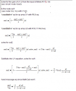
Back to the subject; I had time to relearn a little MATHCAD last night (I actually bought a full licence which is a little pricey but there might still be a student version). The functional form for the diff-pair of ideal FET's is A*Vin*(B-C*Vin^2)^1/2. This is a nice odd function where A, B, and C are related to Vp, Idss, and bias. It also has a nice Taylor series expansion. You can even just substitue sin(x) for Vin and get an exact harmonic series with all the terms gathered neatly. This is incredibly tedious to do by hand. When I figure out how to post the full results without retyping all the answers I will post them.
This looks very promising. You can have an expression for each harmonic in terms of input level, Vp, Idss, and bias in full symbolic form.
BTW I will point out again that you could hand enter a circuit into any massive simultaneous equation solver, for instance one that astronomers use to model galaxies and get the same answers.
Back to the subject; I had time to relearn a little MATHCAD last night (I actually bought a full licence which is a little pricey but there might still be a student version). The functional form for the diff-pair of ideal FET's is A*Vin*(B-C*Vin^2)^1/2. This is a nice odd function where A, B, and C are related to Vp, Idss, and bias. It also has a nice Taylor series expansion. You can even just substitue sin(x) for Vin and get an exact harmonic series with all the terms gathered neatly. This is incredibly tedious to do by hand. When I figure out how to post the full results without retyping all the answers I will post them.
This looks very promising. You can have an expression for each harmonic in terms of input level, Vp, Idss, and bias in full symbolic form.
Sounds very good. MathCad is really very powerful tool. It would be also nice to cover non-ideal behaviour, like channel length modulation etc.
scott wurcer said:[snip]Back to the subject; I had time to relearn a little MATHCAD last night (I actually bought a full licence which is a little pricey but there might still be a student version). [snip]
The Student version of MathCad v. 13 (!) is just over $ 100 IIRC.
Jan Didden
PMA said:Sounds very good. MathCad is really very powerful tool. It would be also nice to cover non-ideal behaviour, like channel length modulation etc.
Unfortunately, it won't do that
 MathCad can't invent a new JFET model. The key is in Scott's The functional form for the diff-pair of ideal FET's is A*Vin*(B-C*Vin^2)^1/2. This is a nice odd function where A, B, and C are related to Vp, Idss, and bias. If it would be possible to provide a closed form of the non-ideal JFET (channel length modulation, etc...), which is a difficult issue by itself, then MathCad won't have any problem to deliver the results, although they may not look so friendly as the nice Taylor expansion of the ideal JFET pair response.
I did last night some measurements on a 2SK170 single stage, exactly as on your web site http://web.telecom.cz/macura/diyaudio/jfets389_SE.GIF (including the 0.1ohm load resistor!) I got 3.0% 2nd harmonic (vs. your 2.2%) and 0.023% 3rd harmonic (vs. your 0.015%). Is this a bad enough match to be worth going into the murky world of advanced FET modelling and parameter extraction? I would say no, but e.g. John may think otherwise.
Ovidiu,
thanks for performirng the experiment on real device, it is very interesting to see your results. It really does not differ much from simulation, I am pleased.
I also have quite good experience with comparison of MC results and real measurements, namely in my class A CFP power output stage based on diamond buffer topology.
Pavel
...Back to the subject; I had time to relearn a little MATHCAD last night ...When I figure out how to post the full results without retyping all the answers I will post them.
This looks very promising. You can have an expression for each harmonic in terms of input level, Vp, Idss, and bias in full symbolic form. [/B]
MathCad screenshot captured in MS Paint accessory, cropped and saved as .png (display graphic, <PrtScrn> button, open Paint and "paste" <ctrl-V>, save as .png or .gif - jpeg sucks for technical graphics )
from: http://www.diyaudio.com/forums/showthread.php?postid=1252873#post1252873
I upload to free PhotoBucket picture hosting service so I can inline larger images
same process can create files that can be "Attached" to posts:
Attachments
Syno8, right you are. You see, Scott Wurcer has worked for the same large company virtually all his life, certainly at least 20+ years. The SPICE program that he has relied on is most exotic and complete, as well as the models that are made specifically for the 'in house parts' that he is designing with. He is in 'hog heaven' so to speak. I even have a Spice simulation from him in my file dated from 1985. I, then, admired the fact that he could emulate circuitry so well.
Within a year or two, I had Microcap on my MAC (they started with Mac in those days) and could make the emulation myself, that Scott sent me. I have ALWAYS relied on computer simulation for differential comparison, transient analysis, and AC analysis. I have tended to avoid distortion analysis, noise analysis, and DC analysis, mostly because of the LACK of sophistication of the computer and program at my disposal.
Now WHY? Well, when I attended classes at the time and place where SPICE was being actually created, I had some simulations run through the computer. They were complementary differential fet circuits. This was 1973. The distortion results were inadequate at the time. It is true, that was a long time ago for many people, but we had already gone to the moon with our primitive technology at the time, developed most of the topologies for the linear integrated circuit, and we engineers, were just putting aside our slide rules for the new HP35 calculator. What many look back to with contempt, and don't remember or realize, is that math has been with us BEFORE computers existed, and that in those early days, if necessary, large mainframe computers were used, at great expense to solve important problems. It was just not available on our desktop. BUT the HP35 was a 'Godsend' and I carried it with me everywhere for years. I developed many of the routine optimization parameters with the HP35, 65, 41, 48 etc calculators, and felt little need for a Spice emulation, which I did not have the money for anyway.
However, if I had worked in a big company like Scott Wurcer does, I would have learned SPICE right away, and maybe even attended special company classes to get it right. Then I too would have leaned on SPICE, rather than my calculator, to do even the menial tasks, and felt good about it.
In my field, however, heavy math is useful to know about, but not so necessary to make a successful circuit. It is also possible that reliance on a computer simulation, rather than a physical model or working out the parameters yourself with calculator and/or a piece of paper tends to make people mentally lazy, and disassociated or even deluded about the design.
You know, the 1000W power amp that was never built, except on the computer screen.
Now where does this leave us? If you have SPICE, Mathcad, Microcap, etc USE IT, but be aware that it is not absolutely necessary, as none of my relatively successful designs were ever made exclusively with it.
I might also say that this controversy started when Bob Cordell challenged me to produce a SPICE model of my JC-1 power amp, months ago, even after 100's, if not 1000's had already been produced and successfully used, as well as independently measured by 'Stereophile'. The absurdity of his demand got me to respond jokingly: "Spice, I don't need no stinkin' Spice" which started the Spice thread, that I occasionally read with interest.
Pavel
I tested various current mirrors configurations but this one gives the best THD/IMD figures (less high order).
Hi, Patrick, about (balanced version) because it’s cheaper as John stated too, it’s just for testing and learning, of course fully balanced must be better in terms of PSRR and power supply requirements/simplicity as well for cancelling H2 (not so important).
Parallel a cap to R26/R27 worst things as the power supply noise is now totally between mosfets gates sources.
(My mother passed away a few months ago, but I am fine now thank you.)
Zinsula
You are right Q9/Q10 helps to linearize Q4/Q9 and “dissociating” output swing at the input devices.
Charles
Yes I know that J74 is discontinued, but I have some (about 50) and as I don’t plan to commercialize anything, for me it’s not a problem at the moment.
Yes I am in trouble with the folded cascode device, fet mosfet bipolar?
As you stated fets are problematic by their generally low Vds. Hitachi mosfet could be the best choice except the P device (triode like) as you stated. Concerning bipolars I don’t remember very well but when I measured differences between mosfets/bipolars a few months ago mosfets seemed to be better best channel separation?), I will carry some new tests. I also could switch from one to other in listening tests.
I could hardly study various designs, simulate them and choose between best numbers… I prefer just setting operating points and roughly refine the design by Spice then, I built them on a breadboard, and carry some measures to optimize devices and values. I listen to them once on pcb (more reliable), and only then, knowing sound differences, I study more in depth the whys and how of the design/devices sound wise and try to find the parameters playing an important task on sound.
Actually I use 2SK2013/2SJ313, quite good complements, the Fairchild FQP7N10/FQP5P10 could be good candidates (easier to find). What would you use as bipolar folded cascode devices, something like 2SC4793/2SA1837 or MJE172/182?
Current mirror BJT ‘s are 2SA1145/2SC2705.
I find this on Dennis Feucht:
http://www.innovatia.com/ACKTS_AD.htm
Which ones are the most interesting? (Quite expensive complete set.) Maybe have you better links.
And this one:
http://www.amazon.com/Handbook-Analog-Circuit-Design-Dennis/dp/0122542401 344$ !!!
It’s why I would like to carry some listening comparison tests between both designs, on one side probably noise and higher order THD at high levels from the active devices (current mirror: 5 junctions!) on the other side poorer PSRR (folded). Which one is less corrupting sound wise? Or at least which technical characteristics are less important or sensitive for the ear?
Testing too Bipolar vs. Mosfet for the folded cascode? Etc… Mpfff!!! Lot of work to come!
Another question to carry this listening tests, is it worthwhile Teflon PCB’s for accurate comparisons?
I tested various current mirrors configurations but this one gives the best THD/IMD figures (less high order).
EUVL said:Richard,
Why not fully balanced?
And how about caps parallel to R26, R27?
Best regards from Oberkochen. Hope all is well.
Patrick
Hi, Patrick, about (balanced version) because it’s cheaper as John stated too, it’s just for testing and learning, of course fully balanced must be better in terms of PSRR and power supply requirements/simplicity as well for cancelling H2 (not so important).
Parallel a cap to R26/R27 worst things as the power supply noise is now totally between mosfets gates sources.
(My mother passed away a few months ago, but I am fine now thank you.)
Zinsula
You are right Q9/Q10 helps to linearize Q4/Q9 and “dissociating” output swing at the input devices.
Charles
Yes I know that J74 is discontinued, but I have some (about 50) and as I don’t plan to commercialize anything, for me it’s not a problem at the moment.
Yes I am in trouble with the folded cascode device, fet mosfet bipolar?
As you stated fets are problematic by their generally low Vds. Hitachi mosfet could be the best choice except the P device (triode like) as you stated. Concerning bipolars I don’t remember very well but when I measured differences between mosfets/bipolars a few months ago mosfets seemed to be better best channel separation?), I will carry some new tests. I also could switch from one to other in listening tests.
I could hardly study various designs, simulate them and choose between best numbers… I prefer just setting operating points and roughly refine the design by Spice then, I built them on a breadboard, and carry some measures to optimize devices and values. I listen to them once on pcb (more reliable), and only then, knowing sound differences, I study more in depth the whys and how of the design/devices sound wise and try to find the parameters playing an important task on sound.
Actually I use 2SK2013/2SJ313, quite good complements, the Fairchild FQP7N10/FQP5P10 could be good candidates (easier to find). What would you use as bipolar folded cascode devices, something like 2SC4793/2SA1837 or MJE172/182?
Current mirror BJT ‘s are 2SA1145/2SC2705.
I find this on Dennis Feucht:
http://www.innovatia.com/ACKTS_AD.htm
Which ones are the most interesting? (Quite expensive complete set.) Maybe have you better links.
And this one:
http://www.amazon.com/Handbook-Analog-Circuit-Design-Dennis/dp/0122542401 344$ !!!
john curl said:… I still prefer resistive loading on the input stage, but I could be wrong at this time, because Charles has done quite well with whatever he is doing. The biggest problem can be noise injection from the active devices. This is where an accurate Spice noise simulation can be useful.
It’s why I would like to carry some listening comparison tests between both designs, on one side probably noise and higher order THD at high levels from the active devices (current mirror: 5 junctions!) on the other side poorer PSRR (folded). Which one is less corrupting sound wise? Or at least which technical characteristics are less important or sensitive for the ear?
Testing too Bipolar vs. Mosfet for the folded cascode? Etc… Mpfff!!! Lot of work to come!
Another question to carry this listening tests, is it worthwhile Teflon PCB’s for accurate comparisons?
john curl said:I have ALWAYS relied on computer simulation for differential comparison, transient analysis, and AC analysis. I have tended to avoid distortion analysis, noise analysis, and DC analysis, mostly because of the LACK of sophistication of the computer and program at my disposal.
John, this is well said. As you might noticed, I use transient analysis to find distortion spectrum, rather than distortion analysis, and I plot "harm" function. In case I use transient analysis, the circuit may have more than one input signal source, as here in case of differential pair. Also, I can influence start time/stop time of analysis, let the initial transients settle, find proper time step, ratio of sample/signal frequency etc. etc.
I hope that the MC9 file is working.
john curl said:
However, if I had worked in a big company like Scott Wurcer does, I would have learned SPICE right away, and maybe even attended special company classes to get it right. Then I too would have leaned on SPICE, rather than my calculator, to do even the menial tasks, and felt good about it. .
No actually when I started it was HP35 and IC layouts drawn with pencil and made with that red photo tape and Xacto knife.
One of our layout guys decided that everone's life would be made easier for all time if there were exactly 2.5 cm to the inch (less typing into the calculator). The old and "new" mask sets never did line up.
You're right about one thing ->
Richard,
> Parallel a cap to R26/R27 worst things as the power supply noise is now totally between mosfets gates sources.
I was not fully awake. I meant R25, R28 of course.
> My mother passed away a few months ago, but I am fine now thank you.
I heard on the forum.
Was what I had in mind when I wrote the last message.
Glad to see you back.
Patrick
- Status
- Not open for further replies.
- Home
- Amplifiers
- Solid State
- John Curl's Blowtorch preamplifier