Multi Layer Ceramic Cap measurements
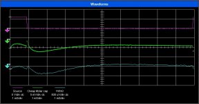
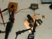
I set up a fixture similar to John Curl's with a few changes to measure the MLC sample I have. I used a Tek 7a22 preamp and a matched pair of P6055 probes to look at the differential. I revised the bridge a little, drove it through a transformer to reduce the HF common mode stuff and created a synthetic reference at approx the differential potential (the reason for the transformer isolation).
The top is the source waveform- a 1 mS pulse with a 10 mS rep rate, the middle is a cheap mylar (I couldn't find a generic X7R Ceramic) the bottom is the NPO multilayer ceramic. The scaling is accurate- the middle is X 1000 and the bottom is X10,000. Getting a balance at these ratios (CMRR of 10,000) at the higher frequencies is very difficult. The differences from the reference cap ( A Component Research film and foil Teflon in a plastic case with pure copper non-magnetic leads) is very small.
Attachments
andy_c said:
In the non-audiophile world, only the gain-bandwidth product is important, and the open-loop bandwidth is irrelevant.
Hi Andy.
I have to nit-pick here. Since gain bandwidth product is equal to the unity loop gain frequency times the closed loop gain, a GBWP figure means rather little unless you know what the closed loop gain is.
Steve Dunlap said:
Sorry, that wasn't my opinion. That was what it measured. Not just one sample either.
Well then your measurement system or technique is probably duff.
Cheers,
Glen
John:
Yes, at least 10X better than the Mylar. I'm really a the limit of measurement with this for now. Possibly lowering the input band limit would make it easier to go a little deeper. I could get 5X more but I'm not sure about the uncertanties of the measurements going that far.
The big NPO's aren't cheap. And asking for 1% brings a huge premium. I'm not sure how to use them commercially yet. And I need to get Asian samples to see if they are consistent in performance.
ostripper said:edit: I do 1k- 10k -20K now ,both at medium and pre clip power.
OS
Good, and In the interests of furthering understanding could you please post the *.asc file of your LTspice sim. I’m sure Andy would appreciate your generosity as much as I. I looked up the Krill thread and downloaded the schematics on the last couple of pages. I’m somewhat annoyed that I’ve just wasted an hour or two investigating this circuit, but that is all I will say for now.
Cheers,
Glen
Glen ,I told andy that I don't have that anymore , since I was most
jealous and frustrated by it. Simulate it yourself, but don't use his input stage.. use what you know is best. This seems to
be like apples and oranges ,as I still am not not sure whether
he (steve) was referring to just the krill current stage or
the whole design (or some unknown mystery design).
I am absolutely objective and would love to gnaw on
that unknown design..
OS
Just a few weeks away and WOW, 45 pages of new stuff to wade through....and ...
Well, it certainly HAS been interesting reviewing the posts of the past weeks...However, I must point out a lost opportunity.....
Are there no punsters among the regulars or visitors on this thread????
It was not all that long ago that we were on page 555 of the thread, and I saw no jokes about the 'timely' nature of posting on that page....Perhaps it was because it might have become a periodicaly repeditive problem, albeit easily programmed...at least as long as that page was active.
We'll all have another chance in the future when page 741 comes up, an equally famous LM to slew limited bandwidth humor about.
____________________
Back to reality..... 2 topics to mention
For years I have relied on a trusty old Spectra Physics spectrum analyzer,...a beast almost the size of a under counter refrigerator. I could look at up to 100KHz through many filter windows, and resolutions, all with push-button simplicity. It was useful for both acoustic and basic electronic stuff but, Alas, the years are catching up with it, and soon I will have to bear the reality of sending it to the resting place for old T&M. The big problem is that I have to start looking for something to replace it with. I'm thinking about 2 units actually, at least in concept..one to look at lower frequency stuff, and another to look into the RF regions, something we did not have to do much of in the pre-CD days when lookin' up to half a meg was pretty much enough to see the junk and design it out. I'm not ready to buy, unless the Gov sends a pile of TARP money, but it IS time to start learning about the specific Mfg.s and models that have proven to exhibit useful characteristics for the kind of higher level design work that is discussed here. ....I would like to see a return to some discussion on the topic. Several of you have access through work, or in your own labs, to some nice stuff. At this point in time, the T&M goal is affordability and usefulness in balance, as the BIG goal these days is fast pay down of mortgage.
This discussion on caps is quite interesting, including the visitation on testing methods. I use my HP 4274A and 4375A every week to qualify and sort parts for L,C,R, Z, Q, D, and more. Darn boxes were about 10 grand when I got them...today from less than 1 grand to about 4 or so in the used market. I highly recommend them, especially so now that they are cheap to buy, comparatively speaking... . The 4274A is the lower frequency range unit, likely more useful for audio work if you could have only one. The newer replacements are easy to use and cal, being under computer control now, but these older boxes still give the results, and seem to be preferred by calibration and standards labs around the world, over the newer stuff.
------------------------------------
.....and the "Food For thought" concept.....
Did the following really happen????? Yup..and the argument still goes on decades later, even here!!!
Many years ago I was privy to hearing a conversation between a gifted professional speaker designer of his period, the 60s and 70s, and a fresh graduate from EE school who felt himself to understand all that "simple" audio stuff...The grad was challenging everything the old pro did in refining his designs, claiming that non of measurements, design goals, and refinement by listening stuff made a bit of difference beyond simple frequency response, and further stated that mere humans were totally incapable of hearing such nuances..The old pro answered with a grin, "Yes you are right...NOTHING I do to improve my work makes any difference at all, we are all basically deaf and hear next to nothing. You see, the Devil put me here to challenge your belief that all the exotic measurements, listening tests, and delicate refinement are useless. You have passed your challenge of faith in your believe, now go play in your OWN Church of sonic religion."
Its kind of like the same idea that some religious folks have that the Earth and Universe is only about 6K years old...that fossils and stuff tens of thousands of light years away in space was "created here" specifically to test and challenge the faithful. The TRUTH will indeed be different, for different people.
Woof!, ya'all!
Keep it decent, but keep it interesting! Now I'll get back to designing ......Lemme see now ....................
john curl said:Looks interesting, Demian. The NPO is 10 times better than the Mylar?
I told you, NPOs aren't all that bad.
Condemnation without examination is prejudice.
Re: Multi Layer Ceramic Cap measurements
Demian,
Interesting and revealing. I might have missed it, but how is this measured? Sending the puls into the cap with the other side loaded to ground? What's the load impedance?
Jan Didden
1audio said:I set up a fixture similar to John Curl's with a few changes to measure the MLC sample I have. I used a Tek 7a22 preamp and a matched pair of P6055 probes to look at the differential. I revised the bridge a little, drove it through a transformer to reduce the HF common mode stuff and created a synthetic reference at approx the differential potential (the reason for the transformer isolation).
The top is the source waveform- a 1 mS pulse with a 10 mS rep rate, the middle is a cheap mylar (I couldn't find a generic X7R Ceramic) the bottom is the NPO multilayer ceramic. The scaling is accurate- the middle is X 1000 and the bottom is X10,000. Getting a balance at these ratios (CMRR of 10,000) at the higher frequencies is very difficult. The differences from the reference cap ( A Component Research film and foil Teflon in a plastic case with pure copper non-magnetic leads) is very small.
Demian,
Interesting and revealing. I might have missed it, but how is this measured? Sending the puls into the cap with the other side loaded to ground? What's the load impedance?
Jan Didden
I run 20dB gain and a few MHz at -3dB.
OL freq resp is a few 100kHz.
Pure class A. 30W.
Sigurd
OL freq resp is a few 100kHz.
Pure class A. 30W.
Sigurd
syn08 said:
Don't worry, that's not the reason 🙂 I am currently running 8MHz unity gain for a 200W power amp, and nobody said anything about lunatic fringeness.
FFT
Okay not exactly an 'electronics engineer', but according to your profile (i.e. your own words) 'Profession: Electronics technician'.
See: http://origin.org/ucs/profile.cfm?uid=114153
Joshua_G said:..................
I'm not an electronics engineer. I stated it over and over in this thread.
.................
Okay not exactly an 'electronics engineer', but according to your profile (i.e. your own words) 'Profession: Electronics technician'.
See: http://origin.org/ucs/profile.cfm?uid=114153
ostripper said:Glen ,I told andy that I don't have that anymore , since I was most
jealous and frustrated by it. Simulate it yourself, but don't use his input stage.. use what you know is best. This seems to
be like apples and oranges ,as I still am not not sure whether
he (steve) was referring to just the krill current stage or
the whole design (or some unknown mystery design).
I am absolutely objective and would love to gnaw on
that unknown design..
OS
OK, but after you edited with this:
"edit: I do 1k- 10k -20K now ,both at medium and pre clip power"
I figured that you were about to simulate it again 😕
I did simulate it (just the OPS) myself and I'm utterly bewildered than anyone else here could have simulated it and found it working as advertised (especially with 0.005% THD), hence my request for your *.asc file.
Cheers,
Glen
You are a hard man to please, MR. kleinschmidt..🙄
It will be in my "WWW" in 12 hours using better devices
with good models (no ON's). (directory .... frugalamp\other)
edit: its there now .. original and just OPS
OS
It will be in my "WWW" in 12 hours using better devices
with good models (no ON's). (directory .... frugalamp\other)
edit: its there now .. original and just OPS
OS
Steve Dunlap said:
Are you saying that only an "audiophile" would bother to design a circuit with a little bandwidth before the application of feedback?
Yes, in general as a "religious" stance. For instance putting a resistor to ground on a perfectly good VAS solely for the purpose of lowering the OLG to a 100k rolloff point rather than 100Hz (made up example).
audiowolf said:Its kind of like the same idea that some religious folks have that the Earth and Universe is only about 6K years old...that fossils and stuff tens of thousands of light years away in space was "created here" specifically to test and challenge the faithful. The TRUTH will indeed be different, for different people.
Funny this analogy keeps coming up. I sort of think of the guy grinding up stuff in his kitchen and baking it in his oven and then wrapping it around his speaker cables explaining the "sonic" results with a heretofore undiscovered quantum grain boundary effect.
After all it's the creation "scientists" that need a new model of the atom to invalidate carbon dating. Sounds familiar to me, Peter Belt, etc.

Re: FFT
So?
Edmond Stuart said:
Okay not exactly an 'electronics engineer', but according to your profile (i.e. your own words) 'Profession: Electronics technician'.
See: http://origin.org/ucs/profile.cfm?uid=114153
So?
I do not understand that turmoil and attacks here. As a technician, and not an engineer, Joshua does not necessarily need to know what is FFT. He asked a normal, polite question, and has got a normal answer. Then a crowd of spiteful posters has appeared.
ostripper said:
Yikes, I would completely redesign that one.
.0005% at 400w/w out NFB , you should be designing ALL the linear circuits for the "big boys". .05% is more realistic, giving
.0003% after NFB. Come on' ..at least divulge the topology for
this magic amp..words are cheap.
(I know it is not the "krill")
OS
I think you have added an extra zero.
- Status
- Not open for further replies.
- Home
- Amplifiers
- Solid State
- John Curl's Blowtorch preamplifier