Hi Joho,
het werk is nog niet gedaan 😉
Could you use a higher resolution for the bmp-file.
It is way too small and enlarging the picture makes it unreadable.
Thanks so far.
het werk is nog niet gedaan 😉
Could you use a higher resolution for the bmp-file.
It is way too small and enlarging the picture makes it unreadable.
Thanks so far.
Well folks, you pretty much have it! This is a simplified version of the line amp that we used in the CTC preamp. Does anyone have a computer emulation of this circuit? I don't, for a number of reasons, but I know what it measures. It would be interesting if the emulation looked almost exactly like the measured output.
Hi John,
Computer simulations would only make sense if the Line Stage circuit is also shown with specific values and component types used. As such it would be interesting to know if you allow such to be shown here.
Furthermore, what kind of simulations would you like to see, for instance frequency plots of output and servo, voltages/currents/dissipation node/probe figures on the schematic, etc. ?
I am not interested in knowing if this circuit works, (I know that already), but how it changes with different values of resistors. There might be an 'optimum' operating point that would be implied by the computer printout that I may have passed over. You never know.
John,
The last stripped Line Stage circuit provided may be close to the original, but that I don't know. Apart from that the only resistor-values we know for sure, the 200 Ohm resistors at the top and bottom of the circuit.
Given your knowledge of the topology and your confirmation as such, it can be turned into something that works. What the other resistor-values are and how many more there may be, including the used JFETs/MosFets, is anyone's guess.
A simulation providing results which equal the real thing as such to me is only possible if a basic circuit with reasonable resistor-values and JFET/MosFet types exist. To my knowledge such is not the case.
Much information has been exchanged in this thread on various topics for which I personally am grateful to those who have contributed and participated so far. But there has also been confusing answers at times putting some on the wrong track which, of course, can be pretty frustrating. The power-supply topic has not been given the attention it deserves. So my impression is that we are somehow stuck with fragmented information which at times was/is confusing to me at least. It would be nice if there are separate threads which address specific topics of the Blowtorch, like the Power Supply, Phono stage, DC Servo, Line stage, etc. I think it can be a good learning experience for all of us and more to the point.
I hope I'm not understood wrong here John, for I'm sure your input here is mandatory. For requested figures you can always e-mail me privately if you provide me the proper data . I also hope I'm not the only one who keeps this thread going.
john curl said:I am not interested in knowing if this circuit works, (I know that already), but how it changes with different values of resistors. There might be an 'optimum' operating point that would be implied by the computer printout that I may have passed over. You never know.
John I think that simulations will not be very useful, and doesn’t mean anything serious in audio, just here the Vds/Id function of Vgs, with SK216/SJ76 spice models… Let us know if you are still interested in some sims.
Curves_SK216
Curves_SJ76
> I also hope I'm not the only one who keeps this thread going.
You are not, at least not morally. Certainly for one I wish this thread goes on for ever. It is too interesting to let die. But I don't have Spice so there is nothing I can contribute now. I tried a couple of time with other bids but there was little or no response. Pity.
I think without John's input, it is hard to keep going. Unless someone starts building soon. (Too late for me, I just finished mine. Will publish eventually.)
In the meantime, please please keep it going. I am sure I am not the only one watching daily.
Ricardo,
Try using measured data. For such a simple circuit, sometime you can do the hole lot in an Excel sheet (which is what I do).
Patrick
Actually, the curves for the j76 do not look OK. They should be more 'triode-like'.
As far as exact values are concerned, I am not giving them out. Not because they are so special, but because I specified, up front, that I was not going to publish the specific schematic of this line amp, as long as I am still producing them. The simplified schematics presented are a good base to discuss the circuit, and even for someone to make something that should work well on an individual basis.
As far as exact values are concerned, I am not giving them out. Not because they are so special, but because I specified, up front, that I was not going to publish the specific schematic of this line amp, as long as I am still producing them. The simplified schematics presented are a good base to discuss the circuit, and even for someone to make something that should work well on an individual basis.
John,
I understand your point of view and I'm not asking for specific data of your design. Sorry if that's how it appeared.
I understand your point of view and I'm not asking for specific data of your design. Sorry if that's how it appeared.
John I did the circuit this w.e. it’s really a very good one!!! 🙂 🙂 🙂 Well I just did one half, my system is not balanced, and the DC servo is simpler, I could just compare it to a fet follower (double SK170, follower/current source). With classical music it's really marvelous, with pop rock it seems to lack a little bit some highs, but I think that it's due to the practice of the other more "aggressive" systems.
It's due to the used FETs!Justcallmedad said:.......with pop rock it seems to lack a little bit some highs, but I think that it's due to the practice of the other more "aggressive" systems.
😎
I want to build one also.
I am sure it is good sounding. Looking at the schematic, there is no reason for it not to be a very good linestage.
Hope to crank one out myself in the next month or so. Just finished the power supply, dual 317/337 regs, feeding C-L-C passive filters. It is good for 100 ma per side easy. Since it is adjustable, shooting for 20 - 22 volts per rail. Limited right now by the power transformer selected to right at 25 volts max.
So please keep the ideas and sims coming. I am thinking of using the ZVN/P 2106 mosfets. These are higher input capacitance, but also higher current.
For courages circuit, how would a 2N5566 fit for the 2SK170V? These can run at 10 ma all day long.
George


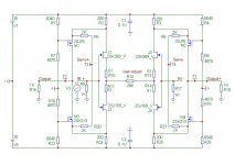
Hello all,
Presenting an individual schematic and simulation plots in following posts.
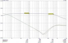
The Line Stage schematic shows voltages on various points in the schematic. DC Servo is a value-adjusted version of Justcallmedad (thanks btw). Frequency plots are from the Output+ and DC Servo +/-.
Of course your comments/suggestions are more than welcome for further improvement.
Presenting an individual schematic and simulation plots in following posts.
The Line Stage schematic shows voltages on various points in the schematic. DC Servo is a value-adjusted version of Justcallmedad (thanks btw). Frequency plots are from the Output+ and DC Servo +/-.
Of course your comments/suggestions are more than welcome for further improvement.
Attachments

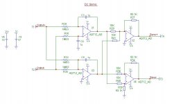
Symmetry?
The pictures of the BT inwards I saw show more caps in the servo.
Why not just 2 servos separately for each branch?
I get confused analysing your servo! At least there should be symmetry in your schematic, which is not there. Rising response of servo beyond 30kHz not good!
courage said:Here's the DC Servo schematic
The pictures of the BT inwards I saw show more caps in the servo.
Why not just 2 servos separately for each branch?
I get confused analysing your servo! At least there should be symmetry in your schematic, which is not there. Rising response of servo beyond 30kHz not good!
- Status
- Not open for further replies.
- Home
- Amplifiers
- Solid State
- John Curl's Blowtorch preamplifier