These are the EXACT parts I was offering to SY. Price, now has gone up.
GLASS with Kovar leads
GLASS with Kovar leads
jacco vermeulen said:Nudes in Space, my ultimate fantasy.
What's the shell made of, Mr Chuck ?
Hi Jacco,
I think it's a hard glass, maybe nonex. The leads are gold plated all the way through the end cap seals to the resistor end caps. The yellow dot on the left was added after the 48 hour burn-in was completed and the resistor passed its tests. Only then could it be assembled into the satellite payload circuitry.
Best, Chuck Hansen
scott wurcer said:I mean to say the guys I hang out with aren't the least bit bothered by the wave/particle issues in fact they eat it up and it's not just for more grant money.
Yeah, I think that stuff was pretty well worked out by, oh, 1930 or so.
In fairness, SY helped me once or twice, but no further.
John, I'd be delighted to help you with anything you like. I'm just not much of a solid state designer, terrible with PCB layout, and don't have Bob's construction skills. Anything else, just ask, I owe you a lot.
Same as Chuck's picture, BUT RN70, 350V, 3/4W. They sure are pretty.
And SY, if you want to do me a REAL favor, just get SE off my ankle. :bs:
And SY, if you want to do me a REAL favor, just get SE off my ankle. :bs:
john curl said:And SY, if you want to do me a REAL favor, just get SE off my ankle. :bs:
If you want me off your ankle, then just stop trying to mislead people that you're measuring cable distortion.
se
SY said:I'll see what I can do about distracting him into chewing on mine instead.
Looks tasty. Is it kosher? 😀
se
SY said:Yes. Let me tell you about cable distortion...OUCH! DAMMIT STEVE! OUCH!
GRRrrrrRRRRrrrr*CHOMP!* GRRrrrrrRRRRrrrr*CHOMP!*
An externally hosted image should be here but it was not working when we last tested it.
PTTHHOOOO!

Ewww.
Tastes like vegetarian.
Hey! Get back here, John!
se
So as a follow up to the ferrous resistor end cap discussion:
I went to be bench and hooked the AP (600 ohm source Z) to a
100 ohm non-ferrous resistor and drove it at 14 ma, measuring
the distortion versus frequency. I also took a spectral analysis
at the output of the AP analyzer with a -140 dB noise floor and a
clear view of the harmonics at about .0003% total.
Then I re-measured with another 100 ohm resistor featuring
steel end caps (verified with a magnet).
No difference in the audio band to the -140 dB resolution of
the equipment.
Nelson Pass said:So as a follow up to the ferrous resistor end cap discussion:
I went to be bench and hooked the AP (600 ohm source Z) to a
100 ohm non-ferrous resistor and drove it at 14 ma, measuring
the distortion versus frequency. I also took a spectral analysis
at the output of the AP analyzer with a -140 dB noise floor and a
clear view of the harmonics at about .0003% total.
Then I re-measured with another 100 ohm resistor featuring
steel end caps (verified with a magnet).
No difference in the audio band to the -140 dB resolution of
the equipment.
Thanks, Nelson!
I guess the result isn't terribly surprising given that even a three foot length of copperweld coax didn't show anything either in Bruno's measurements.
And of course it's perhaps also worth noting (cue Jam) that the AP achieves the performance that it does in spite of it using nickel-cored output transformers. 😀
se
It is the 'ISOLATION' provided by these transformers that helps make the test different from real conditions.
Nelson Pass said:So as a follow up to the ferrous resistor end cap discussion:
I went to be bench and hooked the AP (600 ohm source Z) to a
100 ohm non-ferrous resistor and drove it at 14 ma, measuring
the distortion versus frequency. I also took a spectral analysis
at the output of the AP analyzer with a -140 dB noise floor and a
clear view of the harmonics at about .0003% total.
Then I re-measured with another 100 ohm resistor featuring
steel end caps (verified with a magnet).
No difference in the audio band to the -140 dB resolution of
the equipment.
Hi Nelson,
what about a different experiment - measure the distortion in the signal through the non-ferrous and ferrous resistors in the presence of a near-by wire with a heavily distorted current (i.e. a power supply rail of a typical class AB amplifier). Would there be a difference in the level of distortion pick-up depending on the resistor materials?
Just a thought.
Cheers
Alex
Barbarella!jacco vermeulen said:Nudes in Space, my ultimate fantasy.
What's the shell made of, Mr Chuck ?
chascode said:The attached photo is an RNC60C 1002FSV hermetically sealed nude resistor, 10k0 1/8W 1% Established Reliability Level "S" (0.001% failures per 1000 hours), vacuum rated for space applications. Argon filled, as I recall. Real pricey!
Best, Chuck Hansen
If one waits long enough something interesting shows up. I now have a new background for my screen.
john curl said:It is the 'ISOLATION' provided by these transformers that helps make the test different from real conditions.
Well, it would help prevent any ground loops issues that may occur when you're measuring actual audio components where you have a power supply and chassis leakage involved. But that's a noise issue, not a distortion issue.
But we're talking about cables here. You're just looping the cable from the ST's output back to its input, yes? If so, if there are grounding issues, then what grounding issues could there be except grounding issues inside the ST's chassis itself?
se
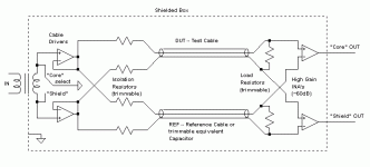
A while ago I've tried to find sound/distortion issues of cables with this setup, which IMO qualifies as a good measurement strategy because it mimizes many issues with seperated or sequential tests and it really tries to test the cables "as such", with the best possible isolation from secondary system effects (shield currents, RFI issues etc). Unfortunately I didn't find any cable effects in spite of the rather high resolution (which I probably could improve some 30dB with what I know now) and I quickly stopped testing, dissapointed from the "non-event" (which btw was not the first effort of this kind, but the earlier two had serious issues -- both systematical errors and noise problems, mainly).
Bottom line: Under that specific conditions I could not detect a differing behaviour between a small variety of cables (1m lenghts) and their lumped RC equivalents, resp. Which doesn't prove anything, I'm well aware of that. And that's why I stopped digging further.
- Klaus
Bottom line: Under that specific conditions I could not detect a differing behaviour between a small variety of cables (1m lenghts) and their lumped RC equivalents, resp. Which doesn't prove anything, I'm well aware of that. And that's why I stopped digging further.
- Klaus
Attachments
- Status
- Not open for further replies.
- Home
- Amplifiers
- Solid State
- John Curl's Blowtorch preamplifier