FWIW in testing electrostatic actuators for microphones I don't see a difference with bias voltage. This is an outlier since these are single ended with a predictable 1.3 % THD. I may try changing the supply on a Quad 63 but I have not seen significant effects from changing the bias voltage. Also a change can take minutes to propagate across the diaphragm.
None of the ESL's I have seen or worked with are designed for maintenance or service. My experience is that anything with at least 5 KV exposed will sooner or later have problems. Most ESL's are quite labor intensive to service and making sure the dust is out is something of an afterthought.
.
Did you know Richard Lees (RIP) in LA? I measured his QUADs and they were really flat. His nor mine are the 63.. ours are newer design with concentric delay rings.
Even so, the 63 are flatter than Stereophile showed.
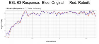
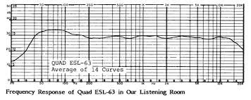
Two different internet sourced plots.
THx-RNMarsh
Last edited:
Did you know Richard Lees (RIP) in LA? I measured his QUADs and they were really flat. His nor mine are the 63.. ours are newer design with concentric delay rings.
Even so, the 63 are flatter than Stereophile showed.
View attachment 816534 View attachment 816537
Two different internet sourced plots.
THx-RNMarsh
The 63 has concentric rings.
//
Much simpler for the people with APs to say, 'the machine doesn't show anything we know should result in claims of imperfection,' or similar.
.
As you can see from the straw poll very few AP users. So not sure where that leaves this argument?
Which raises the question that Jakob(x), yourself, and all proponents of the Golden Ear concept are dancing around: when designing a sensory test to figure out an audibility threshold, what is the hypothesis to be verified by the test? For the sake of an example, assume the threshold is 0.01% 3rd harmonic distortion @ 1KHz, and nothing ele.
....blahdieblah..........
Etc... etc... etc... And when every argument fails or is dismantled, fall back to the immutable stance of "there is not enough money to put into research, so you have to trust my experience".
There's more here than could be put in a few sentences, but I guess everybody got the drift.
As I tried to bring across earlier: auditory tests in the audio industry are done for a reason, that is, to decide what makes stuff better. And, if something makes stuff better, is it worth the extra investment?
There is no epistemological debate behind this. Nor should there be. There are questions of sensititivity, repeatability and practicality, all connected to methodology, but these are of an entirely practical nature.
Fair remarks, thank you.
From the perspectives of some of the people frequently maligned around here, many of us start from the position that we hear things that are not imaginary and that are demonstrably affected (to people that listen carefully) by audio equipment design choices, including in equipment that measures very well as shown by AP tests.
Whether we here what we do because of trained listening, inadequate AP measurement protocols, real world combinations of equipment under non-laboratory conditions, some factor not listed, or some some combination of the above, we don't claim to know.
If you want a guess, it would be 'some combination of the above.' Trained listening does seem to help, as one factor.
We don't offer proof, or scientific evidence of our claims because it is hard, expensive, and time-consuming to do good quality human subject testing.
Much simpler for the people with APs to say, 'the machine doesn't show anything we know should result in claims of imperfection,' or similar.
The strange thing from a scientific perspective is that the second group above, the group with the APs, has some members that believe that the machine shows anything and everything that can be audible to any human on earth. Therefore, they jump to conclusions that all people in first group are mistaken or up to no good. Furthermore, some plainly admit they hate people that are up to no good, so they hate a number of people in the first group. The second group also thinks of themselves as being scientific, 'objectivist' they call it.
The so-called objectivists don't seem very objective or scientific to the first group above.
But, there is NO excuse for sloppy methodology. It is all in the 'demonstrably affected'. In none of your posts have you ever given acceptable proof, nothing has been demonstrated.
The reason you don't give proof is NOT because it is hard, expensive or time consuming. It is because you are chasing dragons. Hard facts will burst your bubbles.
Dear JN,You must understand the technical points a little clearer.
I pointed out the difficulties inherent in a physical system caused by a never before considered aspect of the drive system, that of a change in the system's response due to actuation force.
All normal motion systems with a drivetrain are at the very least, a fourth order low pass. Taking the endpoint (output) as the feedback point requires making sure you are below unity gain before the output phase goes past 180 degrees phase shift. A fourth order will go well past that shift at some point.
My discussion was to detail how the fourth order filter I work with changes it's response physically based on output force,and discussed how an E drive may also change it's frequency response as the HV changes value.
I am not mixing fruit, I am explaining a physical model in electrical modeling terms that most here will understand.
Understand the technical aspects of what I describe, and move on to actual ESL testing.
Jn
It is you who must understand things not just a little bit but very much clearer.
So far you have not shown the smallest know-how in the working of an electrostatic speaker, with remarks like: "the audio signal current is charging the membrane", "PID loops", "instability", etc, etc.
In no way have you even attempted to come with an explanation why a higher AC Mains in the ESL63 would lead to a larger BW.
So next time prepare yourself better before you take part in a discussion and please stop with bombastic mentioning over "never considered before aspects" and "fourth order motion systems".
You may not be mixing fruit, but you evade to coming to the point by randomly mixing pompous words with no substance, just like you did with the previous cable discussion.
And then the last sentence "Understand the technical aspects of what I describe, and move on to actual ESL testing".
This is the most patronising I have ever seen, with the only purpose to level yourself miles above everybody else.
Hans
The 63 has concentric rings.
//
Does it? I have newer 989, I just recalled.
Spec is to be down less than 6dB at 21KHz.
The Stereophile is way way off from spec. Nor does it jive with other's data.
anyway, thats another issue I cant do anything about. But, I would not yet assume the QUAD drops like a rock as Stereophile shows... that would sound really dull. Which it doesnt.
What we saw in L.A. was when line voltage was too low, HV was too low and HF response started to drop at some ac line level which i do not know what. Our listening tests of DUT was done with line voltage which produced a flat response to 20KHz.
-RNM
Last edited:
Richard,Did you know Richard Lees (RIP) in LA? I measured his QUADs and they were really flat. His nor mine are the 63.. ours are newer design with concentric delay rings.
Even so, the 63 are flatter than Stereophile showed.
View attachment 816534 View attachment 816537
Two different internet sourced plots.
THx-RNMarsh
Is this the Richard Lee from the Ultra Low Noise MC Head Amp ??
If so, sorry to hear.
Hans
Does it? I have newer 989, I just recalled.
Spec is to be down less than 6dB at 21KHz.
The Stereophile is way way off from spec. Nor does it jive with other's data.
anyway, thats another issue I cant do anything about. But, I would not yet assume the QUAD drops like a rock as Stereophile shows... that would sound really dull. Which it doesnt.
-RNM
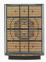
Quad has currently two models, the 2812 exactly as the ESL63 with 4 panels of which the middle ones have their concentric rings, see image below taken from an ESL63.
The 2912 has two extra bass panels, 4 instead of 2 for the smaller models.
The difference is that they are now made in China with a modernised look from the outside.
The 989 that you have is the current 2812 and technically still an exact copy of the ESL63.
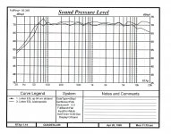
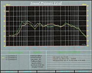
FR of the ESL depends largely on the acoustics of the room used.
Below two images.
The first shows a FR in my previous house without any correction.
Two recordings, One from 84cm distance and one from my listening position showing a drop of -5dB at 20Khz.
The second the FR in my current workroom.
Green is with no correction, Yellow with -5dB at 60Hz and Magenta with an additional lift of 3dB at 170 Hz.
Despite all, the HF part shows a drop of 12dB at 20Khz as taken fom my listening position, 7dB more than in my previous hobby room.
I don't now how Stereophile's room looks, but it looks like a non optimal one for ESL's.
Hans
Last edited:
But, I would not yet assume the QUAD drops like a rock as Stereophile shows... that would sound really dull. Which it doesnt.
Oh, that's probably due to the big membrane and the farfield/nearfield difference. The big membrane do favour the propagation of plane waves which have less ( half) SPL loss when augmenting the distance, in respect to point source sources that make (quasi - we're talking about perfect sources so a well behaving 3 way is the model) spherical propagating waves.
BTW I never heard an electrostatic nor monsters such JBL M2 😛
That's exactly the reason for the concentric rings, individually driven with a certain delay, to let the speaker act as a point source instead of one big flat panel.Oh, that's probably due to the big membrane and the farfield/nearfield difference. The big membrane do favour the propagation of plane waves which have less ( half) SPL loss when augmenting the distance, in respect to point source sources that make (quasi - we're talking about perfect sources so a well behaving 3 way is the model) spherical propagating waves.
Hans
Richard,
Is this the Richard Lee from the Ultra Low Noise MC Head Amp ??
If so, sorry to hear.
Hans
I hope not.
https://www.diyaudio.com/forums/members/kgrlee.html was residing in Australia, his last post was from there on Oct 7, 2019.
And I don't think he has the Quads.
I sent him a PM though 🙂
George
Actually, no. Stating such drivel does not help you understand the engineering any better.Dear JN,
It is you who must understand things not just a little bit but very much clearer.
So far you have not shown the smallest know-how in the working of an electrostatic speaker, with remarks like: "the audio signal current is charging the membrane", "PID loops", "instability", etc, etc.
In no way have you even attempted to come with an explanation why a higher AC Mains in the ESL63 would lead to a larger BW.
So next time prepare yourself better before you take part in a discussion and please stop with bombastic mentioning over "never considered before aspects" and "fourth order motion systems".
You may not be mixing fruit, but you evade to coming to the point by randomly mixing pompous words with no substance, just like you did with the previous cable discussion.
And then the last sentence "Understand the technical aspects of what I describe, and move on to actual ESL testing".
This is the most patronising I have ever seen, with the only purpose to level yourself miles above everybody else.
Hans
This is not the first time you've not understood the actual technical points, nor I fear will it be the last. You seem to always discount what you do not understand despite being given a clearly described explanation such as the precursor I provided as a basis. Stating a neon is a short circuit protection is an interesting data point.
An estat driver can easily be made with external plates as field bias, internal as modulator, so that strawman is useless.
As to stating I do not understand because I speak of PID loops...what a large strawman that is. I detailed some of what I actually do for a living as a technical explanation of what an actual physical system does, how it is modeled, what it's transient response to forces are, and how those system reactions have to be compensated because of shifts in amplitude/phase resulting in excessive phase margin. The key takeaway for you should be the system response to time varying accelerations, but you miss that in your thinking.
Your response tells me you have either no ability to engineer physical systems, or no desire. But a real desire to put down anybody who dares present understandings beyond your experience. You may be good at what you do, whatever that is, but you clearly have no desire to extend your knowledge.
Oh, and patronizing? No, it is not. The first half is a statement of fact, the second is a desire to move on as you cannot understand what I detailed, so stop muddying the discussion with erroroneous info and move on.
Jn
Last edited:
Quad has currently two models, the 2812 exactly as the ESL63 with 4 panels of which the middle ones have their concentric rings, see image below taken from an ESL63.
The 2912 has two extra bass panels, 4 instead of 2 for the smaller models.
The difference is that they are now made in China with a modernised look from the outside.
The 989 that you have is the current 2812 and technically still an exact copy of the ESL63.
FR of the ESL depends largely on the acoustics of the room used.
Below two images.
The first shows a FR in my previous house without any correction.
Two recordings, One from 84cm distance and one from my listening position showing a drop of -5dB at 20Khz.
The second the FR in my current workroom.
Green is with no correction, Yellow with -5dB at 60Hz and Magenta with an additional lift of 3dB at 170 Hz.
Despite all, the HF part shows a drop of 12dB at 20Khz as taken fom my listening position, 7dB more than in my previous hobby room.
I don't now how Stereophile's room looks, but it looks like a non optimal one for ESL's.
Hans
View attachment 816554 View attachment 816555View attachment 816556
Normal speaker measurement is at 1 meter and with a minimum of room influence. Otherwise, every ones far field data will be totally useless for comparisons. But maybe they did measure it in far field of some unknown room characteristics. Big Boo-Boo IMO.
THx-RNMarsh
Last edited:
Hmmm. If it's a ring structure to create a pseudo spherical wavefront, and the bias sheet has significant resistivity requiring a long charging, can the audio signal capacitively modulate the center membrane sufficiently to change the wavefront geometry? Is the center membrane a film with deposited conductance on both sides, so capable of supporting a differential voltage through it's thickness? That would imply a directivity vs DC voltage level caused by lateral gradients in the bias film charge. Again, that would depend on the film electrical time constant and assumes the recent statement of film bias settling time is accurate.What we saw in L.A. was when line voltage was too low, HV was too low and HF response started to drop at some ac line level which i do not know what. Our listening tests of DUT was done with line voltage which produced a flat response to 20KHz.
-RNM
Polar plots vs DC bias would be the tell.
Jn
Last edited:
Richard, just had an odd thought..
Is the center film coated on both sides or only one?
I ask because I use kapton films for quench spreading heaters on the niobium tin quadrupoles, they are metalized only on one side. We hi pot them to 5kv using a conductive brush wand as a pinhole would be destructive in 4.5 k helium.
During hi pot, the backside of the kapton is capable of supporting huge charge gradients, to the tune of kv per cm, and if the ambient is below 20 RH, it will hold it for days. I stress in my hi pot training class to short the entire surface much longer than the hi pot test time, as kapton is also notorious for dielectric absorption and will recharge 20 to 40 percent of test value after being directly shorted.
John
Last edited:
- Status
- Not open for further replies.
- Home
- Member Areas
- The Lounge
- John Curl's Blowtorch preamplifier part IV