Why is it, that manufacturers don't provide this information? All spec sheets of amplifiers I am aware of show the same noise dominated down slope of THD+N.
The parameters provided by manufacturers (in general, with very few exceptions) are close to useless and I believe it is intentional. Atkinson started to show THD (without N) plots few years ago, as SYS2722 + appropriate SW module allows for this. So you need to read very carefully which plot was posted in the review, as he still uses both.
If you are so against output inductor on the PCB board, do you have measurement to show how much THD will increase with output inductor on the board comparing with output inductor far from the PCB board?
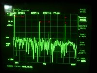
It's very hard to extrapolate, since the result depends on the amplifier load (current through the coil), output power, overall 2nd harmonic distortions (if that's rather high, you will barely see an improvement), coil diameter and length, amplifier wiring, etc... But sure, attached is the distortion spectra with the output inductor off board. After removing the inductor, the 2nd harmonic went down by 19dB (almost 10x less 2nd harmonic, at this very low level).
3 pairs of lateral mosfets, biased at 150mA each, 100W/8ohm, coil is 15mm dia and 25mm long (2.5uH) amortized by 3.3ohm, frequency is 20KHz, THD @20KHz with coil on the board 0.001%, coil on board, and 0.0001% with the coil off board (as shown). It is expected the on board coil effect to scale more or less linearly with the current, so with the square of the output power.
This was an extremely careful construction (the PGP) with regards to stray magnetic fields and induction (bringing a steel screwdriver around the on board coil was immediately visible in the distortion spectra, as a 10-15dB extra increase in the 2nd harmonic distortion). I can't even imagine what would be the effect for a conventional amplifier wiring, since I never placed an output coil on the board since, not even for much more relaxed YAP amp.
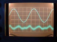
P.S. Found another pic, the 20KHz distortion residuals, with the coil off board. As you can see, almost entirely 3nd harmonic. 2rd harmonic due to magnetic effects are the small ridges in between, placed at the load current peaks.
Attachments
Last edited:
Haha really "difficult" task from feet to m 😀
BTW, imperial units are used in USA, Palau, Marshall Islands, Micronesia and Belize. The "rest" of the world uses metric units 😀
Except for our split personality in Canada. Kilometers on the highway, feet and inches with lumber, Celcius for weather, ferinhiet for the oven, grams for buying food, pounds for your weight. History and our close ties to the USA make it hard to let go of imperial. At least were good at converting between the two.
Not quite. In crazy Canada we still have lumber, drywall and even pipes and valves in Imperial measurement!😛
That's on purpose, to force everybody buy tools in both metric and imperial, good for the economy
 . It drives me nuts, I always pick the wrong type.
The RME ADI-2 PRO is about $2,000.
The Allo USB dac is expected to be under $200.
The non-PRO version of ADI-2 is another story if that's what you are thinking of. I personally would not buy one for hi-fi, but I would use one for measurement applications. Also, they are SPDIF only, unlike the PRO version which includes USB.
Haven't tried the dac-only version myself.
It has usb 2.0 (non pro) $1,000. Native dsd to 256
ADI-2 dac tests out close to the top over at ASR....they all love it.
I didn’t realize Allo was the pie people......never really had much interest in miniature stuff.
Last edited:
Except for our split personality in Canada. Kilometers on the highway, feet and inches with lumber, Celcius for weather, ferinhiet for the oven, grams for buying food, pounds for your weight. History and our close ties to the USA make it hard to let go of imperial. At least were good at converting between the two.
And prepackaged whatever has usually, as labeled, 454grams.
Yes the metric/imperial nuts, bolts, allen keys drill bits etc. is anoying and here its about half and half.
I (can only) hope so. Notice the “thermal interaction” in their CHT technique.Do they take account of the fins facing each other do not radiate into free space?
using the conjugate heat transfer transfer technique, abbreviated as CHT. Conjugate heat transfer defines processes which involve variations of temperature within solids and fluids due to thermal interaction.
Scott, check the 4rth picture from the bottom on this sim, I think it shows what you’ve asked.
SimScale
At 20 hertz the magnetic skin depth in aluminum is just over 1 centimeter.
Ed, I only know of skin depth related to eddy currents.
This, for pure aluminium at 20Hz is 58mm. For copper 46mm.
George
Bob,
I have one since about 2 years and it is great, what can i say? For use as a measurement input device, it is not far behind pro gear like AP. For music reproduction, it is flawless. I something happened with the one I have, I would order a new one tomorrow.
Thanks vac!
Is there phase adjustment in dsp? I read it held zero phase through the outputs no matter settings but didn’t know if it could be manually manipulated in dsp?
Also is the volume part of the analog out or is that fixed....in other words could it be used as a preamp?
By now, so many of you are on my ‘To Ignore’ list that this thread has become well nigh incomprehensible.
So I’m out of it. Nighty-night, kiddy winks! ToS
So I’m out of it. Nighty-night, kiddy winks! ToS
I have seen an article, in the website, comparing different fins simulations with real life. Something around 16% error, but the curves look similar. Not so bad ?Do they take account of the fins facing each other do not radiate into free space?
When I was still involved with power mosfet semiconductors, we bought in a thermal simulation package (very expensive at the time c. 2002/2003) to look at this issue as an adjunct to a research program one of the PhD's in the team was doing to look at hot spot issues arising from inductive energy dump in power mosfets that under extreme cases could lead to field failures. The issue was how to characterize the device capability and how to reduce to occurrence of 'hot-spotting' in the avalanche mode.
Anyway, for a typical high power amplifier heatsink with vertical fins, the correct place to mount the power transistors is in a straight line 1/3 of the way from the bottom. This will result in the most even temperature spread across the heatsink. Anywhere else and you get 'hotter' than necessary spots and loss of efficiency vis-à-vis heatsink area.
Anyway, for a typical high power amplifier heatsink with vertical fins, the correct place to mount the power transistors is in a straight line 1/3 of the way from the bottom. This will result in the most even temperature spread across the heatsink. Anywhere else and you get 'hotter' than necessary spots and loss of efficiency vis-à-vis heatsink area.
Not according to Rod ESP - Heatsink design and transistor mounting
BTW who uses Belleville washers?
No LIFePo4 battery (size 26650) in that test but note that the bigger the battery, the lower the noise - size matters 😀 Many possible reasons for this (lower impedance, higher current storage, larger surface area for anode/cathode interchange, less chemical reaction noise, etc) but I would suggest that the term 'stability' encompasses all of them
I have added Samsung Li Ion 18650 somewhere in a thread in the power supply section here; no time to search it now. They can hold the candle to the large NiCds. The stronger than 1/f rise at low frequencies goes on the pre amp; I've got the boards for my new JFET amplifier on Monday; two channels with much less noise current with one common input will allow cross correlation in the Agilent 89411A; that brings the noise low enough that I can see the thermal noise of a sub-Ohm resistor. But first I take a few days off in Provence.
Then there will also be an update of the battery article.
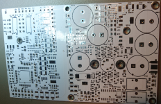
Yes , I put the cross at "I don't care about solder mask color", but white is ugly. 😱
( 1 IF3602 or up to 16 BF862-alikes. No AC feedback in the input which opens a new can of worms,
but also no negative input impedance at 1 MHz.)
Attachments
Last edited:
They are great washers we have used them for years when they flatten you know you are done. They are also secured with a torque wrench but you can get by with hand tightening alone if you want.
I've got the boards for my new JFET amplifier on Monday; two channels with much less noise current with one common input will allow cross correlation in the Agilent 89411A; that brings the noise low enough that I can see the thermal noise of a sub-Ohm resistor.
Good, now this makes sense 😀. Curious about the results, in particular how good the noise correlation is. To my experience, not that great, unfortunately.
Thanks, it confirm tests we made long years ago.for a typical high power amplifier heatsink with vertical fins, the correct place to mount the power transistors is in a straight line 1/3 of the way from the bottom. This will result in the most even temperature spread across the heatsink. Anywhere else and you get 'hotter' than necessary spots and loss of efficiency vis-à-vis heatsink area.
I first read about them here http://www.ti.com/lit/an/sboa020/sboa020.pdf when I wanted to mount some old Hitachi lateral mosfets, used them ever since when mounting to maintain pressure over expansion and contraction cycles.They are great washers we have used them for years when they flatten you know you are done. They are also secured with a torque wrench but you can get by with hand tightening alone if you want.
Ed, I only know of skin depth related to eddy currents.
This, for pure aluminium at 20Hz is 58mm. For copper 46mm.
George
George,
Pavel used mm at 50 hertz to make his calculation look larger! As the skin depth decreases by square root of frequency, his calculation is not to far off from my measurements.
I have posted what I found from transformer leakage measurements and a bit the last time someone posted aluminum wasn't useful as shielding
My aluminum samples I use were alloy 5052 which is common for sheet aluminum. The steel sheets I compared it to are what I get as 30,000 psi precision steel. I might be able to find a data sheet on it. It is also used as sheet steel and the precision part comes in as in has extremely consistant bending. If the yield strength varies then the final angle of the bend or stamping changes.
I think the number you are using is four times the skin depth and the common engineering use.
So I will stick to my measurements and be glad to look at any others.
Still I think the solution is not shielding but proper magnetic design of the inductor.
BTY my method was simple. A send coil, a receive coil and a gap. Easy to vary frequencies and compare effectiveness of different thicknesses and types of materials.
Last edited:
Unfortunately Rod is wrong on this one. But let’s leave it at that because I no longer have the sim results.
- Status
- Not open for further replies.
- Home
- Member Areas
- The Lounge
- John Curl's Blowtorch preamplifier part III