I’ll have what he’s smoking. 🙂
pffft..
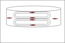
OK...main vc current is right to left.
At each edge, the comp coils are opposing the vc current, but aiding the center current. Net force caused by the comp coils is zero.
When an edge starts to leave the gap, opposing conductors are losing force, but the comp coil center coil is not. So any force the main coil loses is compensated by the force imbalance happening with the comp coil.
Of course, what is actually built here is an underhung geometry with twice the mass and half the force...
sigh, no free lunch..
edit...but I still love the single turn used as a d(BL)/dt sensor.
Jn
Attachments
Last edited:
I was thinking those coils are in sort of the same orientation as the eddy currents in an aluminum former.
I've never tried to solder to a conductive pen trace.
Also, the G force is huge as well as the temperature excursion. Not sure if the conductive pen would survive the environment.
Oh, another thing. Since it is a one turn coil, it would also be simple enough to use a sine signal in the coil, measure the inductance resulting. Because the coil is orthogonal to the vc coils, it won't couple to the actual music. The only caveat to that is when the coil wire leaves the gap, the other side will still be in and the axial forces no longer cancel. But I assume a 10 to 20Khz signal wouldn't be evident in a woofer coil anywhoo..
DC could also be used, whoa, wait...
patent time..
If the coil is the same guage as the vc wire, and the audio signal is run through it in series with the main vc...hmm
When front and back of this coil is in the gap, the forces cancel. If one edge begins to leave the magnetic field, it's forces will reduce, so the net force will be the other edge of the coil.
If the turns are done correctly, I bet it would be possible to compensate out the BL lowering..All it would require is that the comp coils are half the vc height, with two placed, one in front and one in back. This scheme requires zero active compensation. and zero iron modifications.
Oh baby, it's miller time..
jn
How can you use the coil former itself? With a slit/split in it.
-RM
Could you do that with conductive pen?
I had an awesome idea. So, everyone knows that the earth is hollow, right? Just bear with me... If we just planted a giant sub in the ground, what would the room modes of the earth look like, what with the atmosphere thinning out into space... Dispersion?
I'll smoke what this guy is having...
//
The sensing coils would be shorted by a conductive former. Making the former the sense loops would help, perhaps the reduction in stiffness wouldn't matter much if the slits were only under the varnished coil. The former could of course have slits to prevent eddy currents and coupling to the sense loops.
Or, thin laser cut adhesive foil applied to the former?
Or, thin laser cut adhesive foil applied to the former?
The sense coil does not go all the way around the former.How can you use the coil former itself? With a slit/split in it.
-RM
jn
Can you get Jam to get me one/some to me?
THx-RNMarsh
I wasn't thinking of sending you an amplifier...
But I'm sure the company would sell you an F7 that you can modify at will.
🙂
What do you mean by signal chopping? Is it the bass coming from a different direction?
Jn
I'm not sure I can find the link, because I learned about it like over 10 years ago I think.
All the Bose mini systems take the incoming signal and chop it up at a really fast rate. They're are turning it on and off. It is their secret to "room filling sound".
Maybe everyone has been sued into taking down the measurements...
Maybe everyone has been sued into taking down the measurements...
Doubt it, they lost the big one to CU. No need to create folklore, without proof of fraud or malice they can't make anyone take anything down.
I wasn't being too literal. Again the measurements were on an old website. I just don't think anyone cares since their systems aren't all the rage anymore.
So are the sense coils only useful with underhung voicecoils, and would they provide useful feedback at low levels or are they mainly just to improve headroom?
The sense coil does not go all the way around the former.
jn
neither would the slit/split..... or cut/partial cut, etc. Any way using the former for the coil so it can be one step or fewer in order to make easy or mass produced. Simpler mfr'ing.
can it be done?
THx-RNMarsh
Last edited:
So are the sense coils only useful with underhung voicecoils, and would they provide useful feedback at low levels or are they mainly just to improve headroom?
Ah, I knew I was confusing things a bit...sorry.
The single turn sense coils would run from edge to edge, and they are used only do provide motion feedback. For example, running a hf signal into the coil, and monitoring the inductance can be used to see the dL/dt component. So even an underhung coil that doesn't go near the field edge but sees a varying inductance can be compensated.
The audio frequency pickup of the coil can be used to calculate the actual position, as we can calculate the velocity the system should be going at, and look at the voltage generated. As BL drops, the sense coil voltage will show that. Not an easy task, but dsp has enough horsepower nowadays.
Both under and overhung coils have an inductance vs position dependence, and the voltage generated by dL/dt is an unexpected source in series with the coil circuit. Comping that virtual source out will reduce distortion.
jn
we've purchased 2 meter long kapton sheets with copper pc board style traces on them as well as stainless traces.neither would the slit/split..... or cut/partial cut, etc. Any way using the former for the coil so it can be one step or fewer in order to make easy or mass produced. Simpler mfr'ing.
can it be done?
THx-RNMarsh
I also see no reason that the vc former could be made with fiberglass and high temp epoxy. I would first place a layer of glasscloth on a cylindrical mandrel, then place the sense coil wires in place, then a second layer of fiberglass. It could either be wet wound, or use a b stage impregnated cloth that simply requires temperature curing.
As a mass production, I would first wind one layer of the copper vc, then the first cloth layer, sense coil, second glass layer, then the second vc layer. If the wire were also coated B stage, the cure would be one step only. I would also recommend two or four sense coils for differential sensing and redundancy. High guage wires scare me in a production enviro.
Carbon loaded cloth could also work for stiffness, but I do not know the expansion coefficient so could not say if it is a good match for the thermal regime. Glasscloth has a TCE very close to copper along the fiber direction.
A hybrid cloth made with glass in the circumfrential direction and carbon in the axial direction will have strength for the acoustic loads, and TCE for the copper wire in the wire axis direction. or a three layer combo using uni weave cloths, glass along circumference and carbon along axis.
Jn
edit: A sense coil design can also be done in 1 to 3 mil stainless stamped to form, and adhered to the first glasscloth layer using VHB tape and appropriate fixturing. Or for the soldering "faint of heart", 3 to 5 mil copper foil instead . Placement is not as critical since it is far less mass than the copper and does not require angular symmetry.
For Le(x), that seems like too much complexity when a well-placed shorting ring can remove a lot of it, and it is not the dominant distortion. According to Klippel, Le(x) is small compared to the other distortions anyways:
http://www.almainternational.org/ya...ses_in_microspeakers_alma_2013-1.10691701.pdf
For Le(x) to be significant you would have to first reduce Bl(x), which seems to be an exercise in futility without a position sensor independent of the motor assembly.
http://www.almainternational.org/ya...ses_in_microspeakers_alma_2013-1.10691701.pdf
For Le(x) to be significant you would have to first reduce Bl(x), which seems to be an exercise in futility without a position sensor independent of the motor assembly.
The sense coil I speak of is independent of the motor assembly by orthogonality. but instead of looking for position, it looks for dB/dt.
If you really want to use a shorting ring (which is of course frequency dependent), the shorting ring still helps in dL/dx albeit in a limited frequency range.
BTW, I note with interest they don't specify the frequency the inductance was measured at. I assume Klipple somewhere somehow did a scan of various frequencies locked rotor with a shorting ring? For myself, I use 20, 50, 100, 200..etc so that the plot on log paper is fairly evenly spaced.
I also suspect that his measurement technique is flawed. Remember, it's not the inductance per se that is the actual problem, it is the change of inductance that an energized conductor sees. So while the meter is giving a constant reading, that will have nothing to do with the energy shedding that occurs as the vc goes in front of the front plate plane.
Proper measurement of the effectivity of the shorting ring requires a two tone test, with extreme care in observing the higher frequency distortion while the lower frequency is driving towards xmax.
Course, Klipple probably did that as well, right???😱
jn
Speakers are interesting, but I just happened upon a piece of TI applications information that reads as follows:
"In listening tests at TI's sound room evaluating different circuit components used in the LM4702 demo amplifier, there was one part whose negative effect on audible signal quality was undeniable. A DC blocking capacitor on the input of the LM4702 degraded sound quality. In multiple listening tests, with different participants and at various locations around the country, the negative effects of even the best film and foil polystyrene DC blocking input capacitors in the audio signal path was confirmed. It is therefore recommended that DC blocking capacitors not be used in the signal path for mid to high-end audio equipment. Where DC offset from another signal source may be a problem then the use of a DC servo circuit that keeps DC offset from appearing at the output of the amplifier is recommended."
This is the document that contained the above information: http://www.ti.com/lit/an/snaa031a/snaa031a.pdf
Thanks for the cool ap note!


More info, easier, is better!
Cheers!
when thinking about old web pages, don't forget about the WayBackMachine
Internet Archive: Wayback Machine
its probably there
Cheers
Alan
Internet Archive: Wayback Machine
its probably there
Cheers
Alan
As a vc heads forward, the flux path the vc flux can take to the front plate gets longer and longer, hence the lower inductance. The Klipple pdf drew the flux lines accurately, the route the flux takes gets longer ( the reluctance increases).
So, when the vc moves forward, the inductance decreases because the reluctance increases.
A shorting ring on the other hand, decreases inductance by an entirely different mechanism. The shorting ring acts as a distributed secondary (shorted of course), and it reduces inductance because it excludes field from the vc. And by exclude, I really mean that the ring carries current 90 degrees lagging the vc, and it dissipates power lagging another 90 degrees. The net result is the dissipation is not reactive to the vc, but real.
During velocity of energized conductors, a shorting ring works totally different from an open space. A simple inductance meter cannot tell the difference.
Begging the question, is the "measured flatter inductance" really flatter in reality?
Jn
Seems like a lot of work to make the special voice coil. Not to mention the efficiency cost from a larger gap to accommodate the other windings. For less effort using available drivers you can implement the metal detector feedback to linearize the system.
Using the metal detector trick and even a driver with a metal coil former works (I have done that in production quantities). Howeve foil or metal cones work better. Most expensive part is a coil. Metal detector circuits are pretty simple: http://www.talkingelectronics.com/projects/200TrCcts/MetalDetectors/images/Image5of PartII.gif They have some potential linearity issues but not serious. The other solution I showed is very linear and not a lot harder to do but the chips are expensive.
I always used a sealed box. The benefits of reflex etc. are trade offs for response extension. The position servo extends as low as you want and the cone stiffness is really high with the loop engaged. The size of the box is more about efficiency than extension.
Mark Brasfield was mostly responsible for the audio stuff at National Semi. He escorted me through their soundroom a while ago. its was pretty serious with several premium speakers etc. Unfortunately its difficult to justify IC level investments for the premium audio market. The few companies that are (ESS, AKM) aren't really expecting major returns. However the China interest in phones with premium sound has paid off well for ESS. AKM and Qualcomm are both trying for that segment as well.
- Status
- Not open for further replies.
- Home
- Member Areas
- The Lounge
- John Curl's Blowtorch preamplifier part III