Step as in a waterfall? Can you elaborate a little on what in a BR box helps that?
Stuffing, high damping factor. But not much help. Over damped, might just as well close the port.😀
Jn
Stuffing, high damping factor. But not much help. Over damped, might just as well close the port.😀
Jn
A friend likes to build TL lines at the driver FS. They seem to sound better than ports pushing for extended range. Thoughts? (The bass typically is strong)
A friend likes to build TL lines at the driver FS. They seem to sound better than ports pushing for extended range. Thoughts? (The bass typically is strong)
No thoughts, whatever is liked..I do like strong bass though..
Honestly, I'm thinking about actually trying an acoustimass system...I assume any street cred I have is gone..😀 granted, the price was, um, ok.
Jn
Watching netflix movies, in front of the fireplace, sipping grand marnier 1880 with someone special...what cymbals?Listen to cymbals on Bose... very confusing.
For casual listening, I'm not that discerning.
But, given the opportunity, I'll certainly pay attention if cymbals are there.
Jn
Last edited:
Cheapest and easiest is PCF, which makes for a negative output
impedance, moving toward a voltage = velocity model.
I have some laying around here. With a little EQ, they are quite good,
and a single resistor change on an F7 will do it.
Can you get Jam to get me one/some to me?
I will be at his house Sunday.
THx-RNMarsh
Last edited:
Unfortunately, as the vc inductance changes based on direction and velocity, that relationship is trashed.Cheapest and easiest is PCF, which makes for a negative output
impedance, moving toward a voltage = velocity model.
A second cowound coil will communicate with the changing field energy, so the distortion remains.
Jn
Watching netflix movies, in front of the fireplace, sipping grand marnier 1880 with someone special...what cymbals?
For casual listening, I'm not that discerning.
But, given the opportunity, I'll certainly pay attention if cymbals are there.
Jn
High hats are weird too. The whole signal chopping thing is really just not good for music.
When it comes to TV/movies, I'm not that particular on sound. I don't think I would be if I was a billionaire. But for music... I have no objection to the stereo costing as much or more than a house.
Even more importantly how does a round earth affect these things?
Mr. Ed,
The above really pisses me off.
Now what am I going to do I always thought the earth was flat.
In any event, I'll drink to that.

But for music...
Moments of intense enjoyment
I would feel blessed just only if my eyes could follow the score.
YouTube
(what investing in audio gear has to do with that?!)
George
As does any highpass which has the same transfer function. Unless FIR is used to speed up the phase response the only way to get fast low bass from a high order design is to tune low (~25Hz) so the "time smear" appears mostly below the relevant frequency range.A reflex cab can be optimized for amplitude flatness steady state, or for step. But not necessarily both. The higher order cabs require a few cycles to get the amplitude seen on sine plots.
All this is for a highpass function alone. A subwoofer that is crossed over at 80Hz or so with the industry standard LR4 introduces a much more relevant group delay in this very importand range wrt speed, from the lowpass behavior. Since a tapped horn is narrowband by design, the lowpass action is the dominant slowing down effect and there is no way to fix that (except FIR).
has made a nice start to my working day 🙂
Talking about inner qualities…
George
Attachments

As does any highpass which has the same transfer function. Unless FIR is used to speed up the phase response the only way to get fast low bass from a high order design is to tune low (~25Hz) so the "time smear" appears mostly below the relevant frequency range.
All this is for a highpass function alone. A subwoofer that is crossed over at 80Hz or so with the industry standard LR4 introduces a much more relevant group delay in this very importand range wrt speed, from the lowpass behavior. Since a tapped horn is narrowband by design, the lowpass action is the dominant slowing down effect and there is no way to fix that (except FIR).
Alignment is always interesting, but that was not the point of my observation.
Once a sound wave has been launched, the position of the voice coil has no bearing on that sound wave. Various topologies deal with that launched energy by multi order filtering, and designers try to deal with that.
My thoughts are...first, how to prevent the distortion at the jump through linearization of the driver, second by exerting some control scheme to counter the nonlinearities actively, and third, some kind of pre distortion method to linearize travel (leadscrews compensation in the motion control world).
Jn
High hats are weird too. The whole signal chopping thing is really just not good for music.
When it comes to TV/movies, I'm not that particular on sound. I don't think I would be if I was a billionaire. But for music... I have no objection to the stereo costing as much or more than a house.
What do you mean by signal chopping? Is it the bass coming from a different direction?
Jn
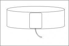
here's a quick pic of what I was referring to earlier on with the dipole coils.
The small rectangular single turn coil is put directly on the surface of the voice coil windings. For a two layer vc, the net current across this opening is roughtly zero, it will not see the magnetic field of the voice coil as it's sensitivity is orthogonal to the solenoidal field of the voice coil.
It will however, see the magnetic field of the gap, as it is poised to see that directly. Note that it's output as it leaves the gap will be of similar nature to the lowering of the inductance of the primary voice coil, perhaps some function that a dsp can work with.
I would recommend at least two coils on opposing sides of the vc to balance mass. Also, I would recommend it be a kapton (polyimide) based printed circuit.
It could also be printed directly on the vc former, that way it would not interfere with the heat transfer across the gap.
jn
Attachments
Could you do that with conductive pen?
I had an awesome idea. So, everyone knows that the earth is hollow, right? Just bear with me... If we just planted a giant sub in the ground, what would the room modes of the earth look like, what with the atmosphere thinning out into space... Dispersion?
I had an awesome idea. So, everyone knows that the earth is hollow, right? Just bear with me... If we just planted a giant sub in the ground, what would the room modes of the earth look like, what with the atmosphere thinning out into space... Dispersion?
I've never tried to solder to a conductive pen trace.Could you do that with conductive pen?
Also, the G force is huge as well as the temperature excursion. Not sure if the conductive pen would survive the environment.
Oh, another thing. Since it is a one turn coil, it would also be simple enough to use a sine signal in the coil, measure the inductance resulting. Because the coil is orthogonal to the vc coils, it won't couple to the actual music. The only caveat to that is when the coil wire leaves the gap, the other side will still be in and the axial forces no longer cancel. But I assume a 10 to 20Khz signal wouldn't be evident in a woofer coil anywhoo..
DC could also be used, whoa, wait...
patent time..
If the coil is the same guage as the vc wire, and the audio signal is run through it in series with the main vc...hmm
When front and back of this coil is in the gap, the forces cancel. If one edge begins to leave the magnetic field, it's forces will reduce, so the net force will be the other edge of the coil.
If the turns are done correctly, I bet it would be possible to compensate out the BL lowering..All it would require is that the comp coils are half the vc height, with two placed, one in front and one in back. This scheme requires zero active compensation. and zero iron modifications.
Oh baby, it's miller time..
jn
Dug out the service manual for my infinity woofer last night. This is my most delayed project as has been hanging around 20 years for me to get around to building the missing bit (the control box). But it was very cheap due to that fact.
Annoyingly the manual has no information on the accelerometer and where it is fitted. Mark 1 eyeball required. I also remain unconvinced that measuring acceleration is the best starting place.
Annoyingly the manual has no information on the accelerometer and where it is fitted. Mark 1 eyeball required. I also remain unconvinced that measuring acceleration is the best starting place.
- Status
- Not open for further replies.
- Home
- Member Areas
- The Lounge
- John Curl's Blowtorch preamplifier part III