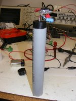
A bad picture of my prototype dust bin full sensor. (Auto focus missed!)
Attachments
Last edited:
Where DC offset from another signal source may be a problem then the use of a DC servo circuit that keeps DC offset from appearing at the output of the amplifier is recommended."
This is the document that contained the above information: http://www.ti.com/lit/an/snaa031a/snaa031a.pdf
So, then it is either a DC servo circuit, or what a fast acting relay to prevent speaker melt down if there is DC in the input of the amplifier?
I can attest to the problem, if anyone has had voice coil melt down.... costly two. In my case two vintage speakers gone, two high end UK speakers gone and two high end UK damaged but still working.
Then if anyone isn't sure, just go around to any of your clubs/venues where live music is played and has a house system. Bringing your own PA amp for plug and play is vorboten.
Where does that leave us? With valerchinco (sp) speaker/amp protection board?
Cheers,
I don't see the relevance of this. If the cone motion is well controlled so is the output, regardless of acoustic loading charactersitics. Only thing to consider is the Q factor of the acoustical resonance(s) fundamental to the design (as explained for the ported case).My point is, any energy that enters the listening space must come from the cone, otherwise a cone position system does not reflect what we hear.
Tapped horns actually present more energy via the back of the woofer, the combined energy cannot entirely be controlled coherently.
You are a well respected person with a lot of knowledge in magnetic design, so if you have some good ideas to improve things the driver manufacturers would certainly listen, especially if your proposals are simple and low-cost.Heck, it's so much easier to fix the BL non linearity mechanically in the magnetic circuit. I'm surprised nobody has done that yet.
18sound, for example, have a technology called "Tetra-Coil" (TTC) -- I seem to recall JBL did a similar thing long ago but the patents have expired by now. It works very well but it isn't as simple and cost effective as one might wish.
Last edited:
A controlled listening test (singleblind) on coupling caps was our first try with this kind of test back in the beginning of the 1980s. Although it was a slightly different position in the chain (being used between a MC head amp and the MM gain/eq stage) we too found evidence for different film caps making a difference. ( I know, i know, that i´ve posted that before, but sometimes some informations tend to get lost..... 🙂 )
Wrt the "o.a dB vs 1 dB" , without any information about the test protocols used by National at that time, it is impossible to evaluate if it invalidates the results.
If the level difference doesn´t manifest as a systematic error, but as an random error it only will raise the noise level (in a statistical sense) in many setups.
Last edited:
Had I taken the time to see what other had contributed I would have seen the issue of beating a dead horse...trying to keep him moving forward, or oxen. Heck just don't ask the Donner party.... Not only did they eat the dead horse, they ate themselves too.
If you hear of a headhunter named Donner, stay away, don't become dinner.
So, me being the jr. achievement member here, how do we wire up a DC servo to a chip, op amp, etc? and Does somebody make a DC Servo on a chip, or a wire in module? or is there a fool proof schematic where even I could implement it? Sober or otherwise?
I'll refrain from my Green Eggs and Ham analogy... but it's just so tempting. ...in a car, ...in a bar, ...on the amp, ...with the vamp....
Cheers,
Back to the shelving for me.
You have any evidence otherwise? I am sure there are some ex NatSemi employees here who could chip in. Personally I think the chances that they did any form of rigorous capacitor testing to be absolutely zero.
Pretty much sums it up.
Much of what Bob Pease and Jim Williams said about audiophiles is unprintable. No point in revisiting this here it won't change anything or anyone's opinion.
There are a few non-cylindric desigs, don't recall who did that right now...I've never seen gap or pole pieces in speakers that were anything other than pure cylinders.
Extended pole piece to balance the fringe field is industry standard, as is undercut pole piece ("T-Pole").Nor, have I seen any reference to a pole piece extending past the front plate.
Also, there is the "XBL" and "XBL^2" motors:
http://loudmagnet.com/html/pdf/XBLPrimer.pdf
http://www.aranmaracoustics.com.au/New_ADIRE/X_68_Motor_Assy_Cut1.jpg
Last edited:
Much of what Bob Pease and Jim Williams said about audiophiles is unprintable. No point in revisiting this here it won't change anything or anyone's opinion.
They might have been right wrt many "audiophile" explanations for something they allegedly have heard.
But in dissmissing the perception of some "audiophiles" they might have simply been out of their field of expertise.
It seems often hard to remember how important it is to seperate these two "things".....
I found this sentence: "1dB level matching has proved to be sufficient." worthy of him.
Tour, thanks for the reference.
That is kind of like a well now author of amplifier books for musical instruments. In my if not all his works he says, "just bypass it with a small capacitor".
Well that is fine and dandy but it depends on what your working with right? Small caps for RF might be a few pFs. If you are working with 1 farad for audio a small cap might be 100uf,
After a few weeks of phone calls I finally got to the author and he said that it was as all small caps should be that is a .47uf cap.
Why not just state what it is to begin with.
Ciao,
If you can hear it, measure it, it makes a difference. Oui? Ja? Yes, Si?
I don't see the relevance of this. If the cone motion is well controlled so is the output, regardless of acoustic loading charactersitics. Only thing to consider is the Q factor of the acoustical resonance(s) fundamental to the design (as explained for the ported case).
Only the energy coming directly off the cone is well controlled temporally. While I agree that the backwave is controlled at the instant, when it comes around, it will be a delayed version. In the event it is a multi-order, the delay can be significant. Group delay tends to make a slow woofer, and no amount of cone position feedback can fix that. For sine only, you are quite correct. I'm thinking transient as well.
Thanks, you need to know that I answer the easy questions. For difficult ones, I have peers...they trash my meager knowledge...😱You are a well respected person with a lot of knowledge in magnetic design, so if you have some good ideas to improve things the driver manufacturers would certainly listen, especially if your proposals are simple and low-cost.
18sound, for example, have a technology called "Tetra-Coil" (TTC) -- I seem to recall JBL did a similar thing long ago but the patents have expired by now. It works very well but it isn't as simple and cost effective as one might wish.
TTC is excellent, well thought out. If they modify the pole pieces profile as per the dipole method I mentioned, they could flatten the bl curve even more. I'm sure they've never modified the gap surfaces beyond cylindrical.
Jn
Ok, I see your point. But as long as everything is linear, the transfer function can be EQ'd to any target (within reasonable limits, you can't fill a cancellation notch etc). The "speed" of a woofer is determined only by its transfer function (visualised as magnitude + phase or group delay frequency resonse aka Bode plot, Nyquist plot, impulse response, step response... it's all the same thing).Only the energy coming directly off the cone is well controlled temporally. While I agree that the backwave is controlled at the instant, when it comes around, it will be a delayed version. In the event it is a multi-order, the delay can be significant. Group delay tends to make a slow woofer, and no amount of cone position feedback can fix that. For sine only, you are quite correct. I'm thinking transient as well.
With FIR filtering one can also adjust magnitude and phase response seperately. This works fine eg for higher order ported designs, like 6th order (4th order acoustical + 2nd order electrical highpass to remove subsonic frequencies below port resonance). Especially when the port resonance is high (50Hz-ish) the 6th order response makes a slow bass but with FIR filters you can "speed up" the response to be equal to for example a 2nd order phase response or even linear phase. Linear phase most often is too much a correction and will sound strange with certain signals as the impulse is significantly spread out in time in both directions ("pre-ringing").
Last edited:
So far, my simple added Re MFB approach is about as simple as it gets and provides significant results. Plus, all DIY'ers can mod their amps to do it in a short time and at lowest cost. I happen to have DVC drivers, so that adds a second - middle or in-between complexity solution.
Cheapest and easiest is PCF, which makes for a negative output
impedance, moving toward a voltage = velocity model.
I have some laying around here. With a little EQ, they are quite good,
and a single resistor change on an F7 will do it.
Much of what Bob Pease and Jim Williams said about audiophiles is unprintable. No point in revisiting this here it won't change anything or anyone's opinion.
There are audiophiles who are essentially nuts in the eyes of critics (apparently erring badly in their attributions), and there are critical listeners who are pretty good at it (understanding what they are hearing). Unfortunately, we seem to have one word in common usage, audiophile, that lumps both groups (and everyone in between) together into one.
EDIT: Perhaps more accurate to say, there is a spectrum with people who largely misunderstand their aural perceptions at one end of the spectrum, and people who are very skilled listeners at the other end. The distribution of the spectrum does not appear to be Gaussian. Again, audiophile, is a word sometimes used to refer to the entire spectrum regardless of which subset of it one may be thinking of.
Last edited:
Ok, I see your point. But as long as everything is linear, the transfer function can be EQ'd to any target (within reasonable limits, you can't fill a cancellation notch etc). The "speed" of a woofer is determined only by its transfer function (visualised as magnitude + phase or group delay frequency resonse aka Bode plot, Nyquist plot, impulse response, step response... it's all the same thing).
A reflex cab can be optimized for amplitude flatness steady state, or for step. But not necessarily both. The higher order cabs require a few cycles to get the amplitude seen on sine plots. Imagine trying to optimize a step response with a tapped horn?
Me, I just inherited a Bose lifestyle 38, acoustimass with 5 baby speakers.. Man, are all of you going to be jealous....😀
Trying to decide if it's even worth trying.. (of course, no remote..)
jn
edit: saw your edit.. It might be that an FIR isn't enough. It may need some weird IIR, especially with a TH.
Last edited:
Yes, it is still necessary to know what and how to measure. And how to interpret the results.If you can hear it, measure it, it makes a difference. Oui? Ja? Yes, Si?
Yes, it is still necessary to know what and how to measure. And how to interpret the results.
Agreed. And there is more than one way to measure. Expensive test equipment is one way, and a good one when such equipment is available. Listening tests may be another way to measure, although subject to more potential sources of error than the first option.
Me, I just inherited a Bose lifestyle 38, acoustimass with 5 baby speakers.. Man, are all of you going to be jealous....😀
Trying to decide if it's even worth trying.. (of course, no remote..)
jn
Someone gave Sidney Harman's aunt a Bose wave radio. She sent him the thank-you note. He wasn't amused. In fact it spawned a competitive product. During the inhouse design phase it was called the Sharp project. Dr Harman objected to the label as Sharp is of course another brand name.
It really stood for "Sidney Harman's aunt's radio project."
Nor, have I seen any reference to a pole piece extending past the front plate.
I have used heavy duty iron door hinge as a phase plug+pole extender (the red one).
Some thick iron washers at the bottom of a wooden phase plug work too.
George
Attachments

A reflex cab can be optimized for amplitude flatness steady state, or for step. But not necessarily both. The higher order cabs require a few cycles to get the amplitude seen on sine plots. Imagine trying to optimize a step response with a tapped horn?
Me, I just inherited a Bose lifestyle 38, acoustimass with 5 baby speakers.. Man, are all of you going to be jealous....😀
Trying to decide if it's even worth trying.. (of course, no remote..)
jn
edit: saw your edit.. It might be that an FIR isn't enough. It may need some weird IIR, especially with a TH.
Step as in a waterfall? Can you elaborate a little on what in a BR box helps that?
From a really old textbook....
V = L di/dt + I dL/dt.
Everybody knows the first, most ignore the second.
When a speaker vc is moving forward, the vc inductance is lowering. As the inductance drops, the energy in the vc, 1/2 LI^2 will shed back into the drive circuit because L is dropping. This is a very assymetrical condition. When the coil turns around and goes back, inductance will rise and the vc will pick up energy from the drive and store it again.
Honestly, I would be more concerned with this phenomena than the BL nonlinearities.
Jn
- Status
- Not open for further replies.
- Home
- Member Areas
- The Lounge
- John Curl's Blowtorch preamplifier part III