A simplified way of speaking. I can speak that way to my physics professor buddies and they get the drift. Obviously, cause and effect don't work exactly that way in reality.
I'm sure we have people here capable of understanding any technical claims you make. So far nobody has stepped up to say Joe is exactly right, everybody should listen to him. Why not?
Because all his ponderings relate to well known and measurable phenomena. It is hard to discuss in a serious manner gobberdeegook.
Has it occurred to you that any impedance above the DC resistance is caused by back-emf, so take any frequency and measure the impedance, and if you also know the DC resistance, you have now made back-emf quantifiable.
I am now aware that others are also looking at the above. Let's not be hasty if it leads to a better understanding of some kind. At least it can't hurt.
This is exactly what I mean. Ever heard of inductance? We don't need better understanding on this issue. Just read up.
Or are you peddling one of your wares, consisting of a speaker with a flat impendance curve?
The fact that SoundEasy, which is a pure maths based program and I would think above reproach, can actually model this as well - makes me very confident (and if you replicated it, so would you).
So can you provide provide a model file for SoundEasy? I daresay someone has it, or there's a trial version?
Interesting. Do you mean no H5 or above or just no H5? What was the non-linearity you used?
I used an ideal buffer with an ax - bx**3 transfer function.
Has it occurred to you that any impedance above the DC resistance is caused by back-emf,
When you start out wrong (totally) where do you expect to go?
Let's see. Antimatter will interact with light, but if gravity is reversed, the interaction with light would be inversed as well.
How would you know there is no negative light? Dark photons that suck energy out of things.😀
I don't see anything wrong with trying a current based setup. But if that isn't the answer, I'm having a hard time seeing how "solving" anything while not switching to a current driven amp, has anything to do with an amplifier.
So far everything mostly reads like "put a big series resistor in with your speaker and plan accordingly in the crossover". I'm not opposed to doing that, either. But surely we can quickly reason why burning off all the extra watts may not be popular.
So far everything mostly reads like "put a big series resistor in with your speaker and plan accordingly in the crossover". I'm not opposed to doing that, either. But surely we can quickly reason why burning off all the extra watts may not be popular.
So this is about the load phase angle/group delay/whatever rather than distortion products of voltage drive?
Joe, why be so cryptic? The only possible result is that no one understands where you're going and you get to look like the smart one in the room. Great way to win friends.
I've used RCs to level out speaker impedance. It does seem to sound better. I think the reactance of speakers in combination with crossover components can create slight resonances that are coerced into propping up parts of the SPL curve.
How would you know there is no negative light? Dark photons that suck energy out of things.😀
Scott, I have a daily experience with the phenomenon. Thanks for putting a name on it.
Just to be clear, I assume the miscreant buffer is inbetween the op-amp output transistors and the feedback cap and the circuit output is unloaded?I used an ideal buffer with an ax - bx**3 transfer function.
I feel your pain, Joe. Even I am having difficulty with what you are trying to describe. Also, I too get criticized by other engineers if I don't use THEIR 'approved' definitions. They must have these definitions ground into their brains from the freshman year in college, and got severe penalties for using a different term for something.
Such as DC resistance. We all know what you are talking about, and it has the further info that that is how you have to measure it. Of course inductance or capacitance can be added to it and then we call it 'impedance'. Big deal, but if these guys can take a cheap shot at you, they will. It isn't really worth it to 'teach' them what you are getting at.
Such as DC resistance. We all know what you are talking about, and it has the further info that that is how you have to measure it. Of course inductance or capacitance can be added to it and then we call it 'impedance'. Big deal, but if these guys can take a cheap shot at you, they will. It isn't really worth it to 'teach' them what you are getting at.
Big deal, but if these guys can take a cheap shot at you, they will.
Was that a cheap shot on your part aimed at people with no intention of doing such a thing?
Regarding impedance and complex algebra, it is a high school math thing. It really is quite minimal to ask someone to make an effort to learn. I think we would be happy to help if there were in fact any interest in learning.
Also, I think a person interested in the field of electronics would find it very useful. it would certainly make it easier to understand quite a lot in the way of many written resources, as well as various discussions by other people in DIY forums, etc. Whyever would someone not want to learn it?
Last edited:
Such as DC resistance. We all know what you are talking about, and it has the further info that that is how you have to measure it. Of course inductance or capacitance can be added to it and then we call it 'impedance'. Big deal, but if these guys can take a cheap shot at you, they will. It isn't really worth it to 'teach' them what you are getting at.
There are actually significantly more complex issues as well.
All speakers will have eddy losses which are frequency dependent, both in the vc wire as well as in the magnetic circuit. If you try to measure these eddies, you must consider the fundamental frequency losses as well as the second harmonic losses. Simple meters cannot distinguish between the wire resistance and the eddy loss "resistance", nor can the meters determine what frequency the losses occur at.
The eddy losses are also dependent on the velocity of the vc in the gap, and will modulate depending on the actual direction of the coil with respect to any higher frequencies the vc is carrying. Meters are incapable of seeing this as well.
The inductance will change with frequency. A vc moving in a gap changes it's inductance. If a charged vc is moved in the gap field, the gap energy stored can be added to or subtracted from depending on the direction of motion. Remember, V = Ldi/dt + I dL/dt..
The acoustic wave travelling along the cone material from the surround back in will also present as an energy storage mechanism, and can either lead or lag. The pressure of the cabinet does the same.
There are no accurate models for real speakers.
jn
Quibbling is what I call it, not what high school you went to. Not all high schools are equal, you should know that Mark. Some us, including me, had to learn it the hard way, but with
later studies and reading. Sometimes, I certainly mix up my definitions, so what? But, the Quibblers will kick in any time they can.
later studies and reading. Sometimes, I certainly mix up my definitions, so what? But, the Quibblers will kick in any time they can.
Joe needs to explain to us what he means by 'DC resistance' and what he means by 'back emf'. This is not a matter of 'approved' definitions, but a matter of meaningful communication; if we don't understand what someone is saying then we cannot agree with it or disagree with it. In this sort of discussion confusion can be caused if existing terms are used with new meanings, either accidentally or deliberately. There is also the danger of tautology e.g. if 'back emf' is anything not included in 'DC resistance' then by definition the total resistance is 'DC resistance' plus 'back emf' - which tells us nothing. Another danger is claiming that two different (but equivalent) ways of looking at the same phenomenon somehow contain separate meaning.
So look at an impedance plot, measure the DC resistance, which is constant with frequency. It is not frequency dependent, but it is thermally dependent, but that is a different topic. Yet the overall impedance is indeed frequency dependent, but clearly not all of it. So if Re is 6 Ohm, the RMS voltage is 6V, then under ideal conditions it should draw 1 Amp. …
If you really want to have an intelligent communication, please start with an impedance sweep of a driver and specify the operating and testing conditions.
Don’t give Mr. Curl the hard time to co-suffer with you due to the stiff, distorted, engineering brains of the participants.
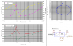
Here is a KEF B110 in a 7lt sealed, non stuffed box. Really basic test set-up from 15 years back.
George
Attachments
Remember, V = Ldi/dt + I dL/dt..
Thank you, but maybe better not to get into such details quite at this point. It's no doubt very interesting and thought provoking to some (I like it), but it can be intimidating to the uninitiated who might benefit from a more incremental and long-winded explanation.
Not all high schools are equal, you should know that Mark.
Okay, IIRC it is part of Algebra 2, at least in Cartesian coordinates. Maybe polar coordinates come later in Trig, don't remember.
Even if not taught in HS or if there were other things going on in life that interfered, it is still something many people can learn without too much trouble.
And as I said, I think we would be willing to help.
OTOH, if somebody has some kind of bona fide learning disability, then I think we could probably make some exception and try to work with the person. But, only so much may be possible depending on the particulars.
Hi John,
So why not, just as an experiment, deal with technical things in an accepted manner. I'll bet you suddenly find that things that caused you some confusion are suddenly crystal clear.
-Chris
Really? Is it worth the creation of confusion to put together a group of "underdogs"? You know much better than this, and if not you're beginning to believe the spin put on things by the flaky hi-end press. We aren't children here, so don't expect anyone to suspend belief in the rules of science that we work with every single day.I feel your pain, Joe. Even I am having difficulty with what you are trying to describe. Also, I too get criticized by other engineers if I don't use THEIR 'approved' definitions. They must have these definitions ground into their brains from the freshman year in college, and got severe penalties for using a different term for something.
So why not, just as an experiment, deal with technical things in an accepted manner. I'll bet you suddenly find that things that caused you some confusion are suddenly crystal clear.
-Chris
- Status
- Not open for further replies.
- Home
- Member Areas
- The Lounge
- John Curl's Blowtorch preamplifier part III