Agreed, thanks George.
I haven't seen non linear high order dimensional analysis like this since the late 70's. Very nice.
Odd the Behringer was not as good as the crown.
I noted the mention of an aluminum split former giving non symmetric axial forces. Certainly agree, but wish they had gone into the motional aspects of eddy braking and possible flux dragging.
But very good as a thesis. Several times he mentions the inability of the test methods used to spot particular items, very worthy..😉
I wonder if any of the work would have been different had he known about using a DVC pickup coil in his research as another diagnostic.
Hopefully, another researcher in the future could answer that question.
Jn
Ps. Tomorrow, I print it out and grab my yellow hi liter and pencil. That'll keep me busy for a while.😀
Last edited:
My GR reciprocity calibrator can use a dynamic mike, a piezo transducer and a condenser mike all at once. It was listed as "absolute" so no higher calibration needed like a Cesium frequency standard.
I downloaded the GR1559-B users manual and there is no mention of dynamic mics. Not to say they are not useful here but I was hoping to find some discussion of how reversible they are or if all the requirements for the reciprocity equations to be valid are still met.
I would stick with the techniques B&K used in the article you posted. I've done it, not sure about doing it at high SPL and still prevent any mutual coupling using ordinary speakers.
The manual its surprisingly light on details and makes the whole process seem pretty simple. Looking into the internal chamber the Shure mike with its logo is facing back. I'll get the beast out of storage and see about more details on the internals. What I don't have are adapters for other microphones.
Using a dynamic microphone makes a lot of sense since it would be fully reversible, would not need external power supplies or high voltages to drive it and the output would be directly compatible with standard instruments (especially 1965 instruments).
If I can figure out the adapters I'll fire the thing up and see what I can learn.
Demian, something is wrong. The chart you put up is for the CAPSULES only and at 140 dB or more! The preamps are subject to cap loading, unfortunately, but with a little care should be virtually unmeasurable even with the capsule up to 100dB or so.
I went back to redo the tests I did years ago on the 2619 preamps. However I sold the measuring amp I used back then and have a newer and much more usable measuring amp today- B&K 2609. With that amp the preamps are very low distortion at a level equivalent to 110 dB SPL from a 1" microphone. The measuring amps do not provide direct access to the microphone output, something I need to change.
Here are a lot of topics common to the current loudspeaker discussion
http://tesi.cab.unipd.it/42449/1/Tesi_Lorenzo_Bortot_-_1014762.pdf
George
Wow! Thanks George! Excellent research.
Howie
Using a dynamic microphone makes a lot of sense since it would be fully reversible, would not need external power supplies or high voltages to drive it and the output would be directly compatible with standard instruments (especially 1965 instruments).
If I can figure out the adapters I'll fire the thing up and see what I can learn.
NIST is off line but IIRC they could offer up to better than .001dB with selected B&K capsules (I think the quartz ones). We sold the MEMS mic group so I lost access to our traceable standards to double check my hack devices. I still can't find any info on how reversible MC mics are (I'm not sure even of electret capsules), speakers will have the additional problem of the back wave.
BTW condenser mics have very different distortion characteristics in open circuit voltage out vs closed loop current out mode (see for instance the B&K article on negative input capacitance cancellation of distortion.).
It’s been some days since I entered into this site for to test the free FEA for magnetics.
Finite Element Method Magnetics: HomePage
I haven’t tried it yet because I am being distracted by reading the “Miscellaneous” section (other sections to follow).
Kudos to David Meeker
George
Finite Element Method Magnetics: HomePage
I haven’t tried it yet because I am being distracted by reading the “Miscellaneous” section (other sections to follow).
Kudos to David Meeker
George
The laminated stack stuff is interesting. Most of our stuff is that.It’s been some days since I entered into this site for to test the free FEA for magnetics.
Finite Element Method Magnetics: HomePage
I haven’t tried it yet because I am being distracted by reading the “Miscellaneous” section (other sections to follow).
Kudos to David Meeker
George
One of the physicists modeled a specific magnet using 98% as the fill factor and permeability. The problem was, the permeability was not isotropic. The permeability along the laminations was indeed 98%. But when field lines had to cross the glue, the net permeability was 2% air, 98 % iron. Oops.
Another nice link, thanks.
John
That PDF is full of great stuff, it corroborates why my model always seems to work best when the magnet permeability is set to 100.
George, were you saying that the saturation point of the magnet is chosen so that the B-H curve is flat? And this reduces BL(i) modulation?
Also I read somewhere that one manufacturer attempted to use shorted turns on the ends of the voicecoil to limit excursion, but that it caused alarming sounds on overload? Can anyone fill in the details on that story?
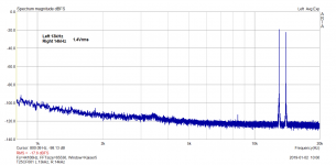
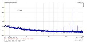
I have decided to try a big 1" condenser microphone for the 13+14kHz tweeter test and it seems to be the right choice. The 1kHz difference tone has gone and 2 driver test is clean now. And, dynamic range is higher - lower noise.
Attachments
Another nice link, thanks.
New action field for your yellow hi liter and pencil
George, were you saying that the saturation point of the magnet is chosen so that the B-H curve is flat? And this reduces BL(i) modulation?
I said that if the steel (*) close to the air gap is magnetically saturated, it’s μr will fall close to 1 thus the eddy currents at the vicinity of the coil and it’s effects will be much weaker (although they will spread deeper into the metal now).
(a common procedure for confirming operation within saturation envelope is to vary H by +/-25% and checking B does not change by more than +/- 1%)
(*) the steel, not the magnet. A PM is saturated only while it’s being magnetized. It’s saturated Bs is about 2.5 times higher that the maximum Br (closed circuit max induction) after removal from the magnetizer . Then as a ready component, the Bd (working point induction) of the magnet is to be set close to ½ Br. (theoretically optimum Br/sq.rt 2 for operation with a fixed air gap for maximum B*H product)
Also I read somewhere that one manufacturer attempted to use shorted turns on the ends of the voicecoil to limit excursion, but that it caused alarming sounds on overload? Can anyone fill in the details on that story?
What you suggest will work only due to eddy currents action but I guess the effect will be weak except at high frequencies and high velocities.
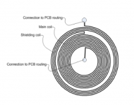
Now, see the attachment for another idea. In the original application (eddy current search probe), it is a coil, the outer ends of which is wound in the opposite direction. This is to achieve some magnetic field guarding or shielding without using ferrite or mu metal around the coil.
In the case of voice coil, such kind of counter winding (now at both ends) will exert a Lorenz force counter to the one that the main body of the coil exerts when these coil-ends reach the magnetic gap.
George
Attachments
Pavel, how about this. Do a 200Hz single tone THD test, calibrated to frequency response and phase. Then post the calibrated .wav file. Say 60 seconds. Since magnetic distortions follow input phase, we should be able to deconstruct the residual into harmonics and that will show us where on the wave the nonlinearities occur.
jneutron will probably be interested in a two tone IMD test, but I'm limited to single tone data.
jneutron will probably be interested in a two tone IMD test, but I'm limited to single tone data.
Great, but unfortunately adding another coil to a tweeter will seriously alter it's characteristics that may render the dvc method unsuitable for most tweeters.... for the 13+14kHz tweeter test and it seems to be the right choice. The 1kHz difference tone has gone and 2 driver test is clean now. ...
Even if it's using wire 1/5th the diameter nested in the valleys of the voicecoil? It seems to me there is room to work there.
I have decided to try a big 1" condenser microphone for the 13+14kHz tweeter test and it seems to be the right choice. The 1kHz difference tone has gone and 2 driver test is clean now. And, dynamic range is higher - lower noise.
Pretty quiet lab? This is as expected, the mic is far better than the speaker.
Pretty quiet lab? This is as expected, the mic is far better than the speaker.
Thank you, yes, though I live in a capital city, fortunately it is a very quiet place and windows have very good acoustic isolation.
Measurements with a high S/N microphone reveals the interesting point - I think that my speakers are a non-issue re nonlinear distortion everywhere but close to and under woofer resonance. The most audible would be IMO the cabinet noises or driver mechanical noises that are non-harmonic. So, there is a question, if it makes much sense to concentrate on driver non-linear distortion in case we use some decent drivers and if the efforts should not be spent to minimize cabinet contribution, just like DW did, and to improve drivers itself re mechanical design, which would lead to very expensive parts, IMO, but might be the right way.
Pavel, how about this. Do a 200Hz single tone THD test, calibrated to frequency response and phase. Then post the calibrated .wav file. Say 60 seconds. Since magnetic distortions follow input phase, we should be able to deconstruct the residual into harmonics and that will show us where on the wave the nonlinearities occur.
jneutron will probably be interested in a two tone IMD test, but I'm limited to single tone data.
I will do it, this afternoon or tomorrow.
- Status
- Not open for further replies.
- Home
- Member Areas
- The Lounge
- John Curl's Blowtorch preamplifier part III