Here are the before and after FFTs for the caterpillar phase plug mod. I'm no expert so I could be drawing wrong conclusions about what is shown, but the effect, at least on FR, seems positive. I didn't notice any harmonic strangeness when looking at the spectrogram. I removed the tape to make the without measurement, so the picture does not show exactly how it was. the tape is scotch 35:
3M 500-49923 Scotch 35 Vinyl Color Coding Electrical Tape, 32 to 221 Degree F, 1250 mV Dielectric Strength, 20' Length x 1/2" Width, Violet: Amazon.com: Industrial & Scientific
3M 500-49923 Scotch 35 Vinyl Color Coding Electrical Tape, 32 to 221 Degree F, 1250 mV Dielectric Strength, 20' Length x 1/2" Width, Violet: Amazon.com: Industrial & Scientific
Attachments
I think they were built for us by E.G.& G. IIRC.
Yes, one of our engineering directors worked on them as his first job out of MIT circa 1962.
All the best toys are under wraps of the weapons/military. Never sold commercially. The BW's were already so high during under ground nuclear testing that fiber optics were starting to be used to transport the "device" detectors to scopes/diagnostics above ground. One situation of the FO became 'clear' was when the FO was used, the radiation from the explosion would darken the FO and distort the data being captured. The amplitude was attenuated and that is significant when measuring the energies, yield etal.
We started a FO lab to study the darkening and maybe what could be done about it or at least cal out the amount etc. The FO researchers needed a wide band scope for thier work and asked their scientific freinds in EU what they used. The French had designed and built only 2 scopes which had such wide bandwidth, I was told we could measure light waves with a scope probe. I contacted the French and learned they only made 2 of them for thier weapons program. No others existed. Our people arranged to have one built for LLNL and sent the money needed for it to be made. It arrived and was about the same size as other large scopes were. wider though and not as tall. Beautifully made.
I can only wonder what is being used today, decades later. The SOTA is far beyond what we are allowed to know.
I didnt think I knew that much but being on events and being in the detonator group designing such things and seeing the device being machined on 5 axis robotic machine etc to ultra high precision et etc..... was enough to prevent me from travelling outside the USA for 8 years after I left LLNL. The data and simulation developments allowed us to stop under ground testing as now we can design a weapon all on computer with accurate results. The laser fusion program also being used in the refinement of the modelling.
Once at the accurate simulation stage.... all the developed hardware -- scopes, timing, triggering systems, pulsers and diagnostic engineering created are no longer needed and only in museums now. Now if we could only cure cancer.
THx-RNMarsh
Last edited:
Do-you remember Orthophase (1960)?A few ideas fron recent (1990's) history-...
An externally hosted image should be here but it was not working when we last tested it.


The guy made at this time a double voice coil boomer, one , traditional, in the back, one, little in the front for servo. The first servoed enclosure I have seen in my life.
Last edited:
I've been here before. Can someone who knows better look at their technology page? How can MEM's with microns of displacement generate any bass no matter how many you have?
http://www.audiopixels.com.au/index...nts-2018/digital-speaker-development-update1/
Actually they may have a small advantage in a way. Obviously you'll need size to get displacement, but the slightly lossy pressure may sound nice and allow feedback to try to reach exertion, as oppose to overshoot first.
However I may not be smart enough to see how it can lower distortion more than a well damped existing type of speaker. It doesn't have motion sensing, and mini magnets are less linear through the mini field. As best as I can tell they're trying to use digital feedback, and DSP may be able to reduce some distortion more than typical with a somewhat lossy device.
Based on the itty bitty speaker they show, I suspect their market isn't hifi, but laptops, phones, and other small items. In that case they should be a huge improvement since suspension systems on itty bitty speakers are obviously bad, and make up half the diaphragm as a secondary flopper.
That's my initial impression, but I suspect someone else will correct me that knows much more than I.
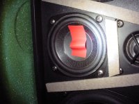
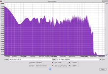
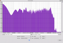
Here are the before and after FFTs for the caterpillar phase plug mod. I'm no expert so I could be drawing wrong conclusions about what is shown, but the effect, at least on FR, seems positive. I didn't notice any harmonic strangeness when looking at the spectrogram. I removed the tape to make the without measurement, so the picture does not show exactly how it was. the tape is scotch 35:
3M 500-49923 Scotch 35 Vinyl Color Coding Electrical Tape, 32 to 221 Degree F, 1250 mV Dielectric Strength, 20' Length x 1/2" Width, Violet: Amazon.com: Industrial & Scientific
Do a water fall plot... see if it is a resonance. I think you will have better luck modifying that surround. IMHO
-RM
Last edited:
I don't have anything that can do waterfall plots. Is there some free software that can do it?
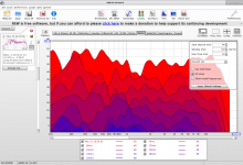
Thanks. I managed to get it working. Unfortunately waterfall plots don't seem to work in Linux. The decay chart shows a notable resonance at 12KHz but nothing I can see that is comparable at 1KHz. I guessed based on my meager knowledge of FFT stuff but these settings may not be optimal for trying to see this.
Attachments

Here is a plot that seems to make more sense for the midrange.
What are you thinking when you say modify the surround?
What are you thinking when you say modify the surround?
Attachments
Last edited:
All the best toys are under wraps of the weapons/military. Never sold commercially.
With the notable exception of the Bybee devices.
Here is a plot that seems to make more sense for the midrange.
it helps a lot to look at other measurement samples to see what to explect. This random example from Stereophile: https://www.stereophile.com/images/618EggAndrafig7.jpg is a start. The total time window is about 4 mS and the steps are maybe 20 uS.
I have encountered similar resonances in drivers and they are usually structural in that they can't be removed simply. In the midrange the 12 KHz may be due to the shape and size of the cavity in fron of the diaphragm. Or maybe the bell mode resonance of the diaphragm. In any case a high Q notch at the resonance may be your best fix.
Here is a plot that seems to make more sense for the midrange.
What are you thinking when you say modify the surround?
apply non-drying damping compound to outer 50% of surround.
-RNM
Speaking of OPPO. OMG does it sound bad, stock. Spitting highs and loss of details like reverb tailing off etc. Sounds just like it was full of electrolytic coupling caps. I go over to OPPO forum and ---- talk is about lots of audio electrolytic coupling caps the signal has to go thru! Very high total DA. Many in series from DAC out thru the audio chain within. Guess they didnt get the memo.
I bought the 105D as a last CD player for legacy CD collection. Nicely built. but what the heck happened to the sound? Compared to even 44.1 copies from the Sony HAP-Z1, it is soooo poor -- very disappointed in it.
THx-RNMarsh
I bought the 105D as a last CD player for legacy CD collection. Nicely built. but what the heck happened to the sound? Compared to even 44.1 copies from the Sony HAP-Z1, it is soooo poor -- very disappointed in it.
THx-RNMarsh
Last edited:
Nice. Now I am not the only one who has listened and understood it is bad. I have seen all kinds of mods. I think the best answer is it is a transport, and you use an external DAC.
A hell of an expensive transport. See What is an audiophile CD player? for measurements on a 10 quid salvaged Sony DVD player. Bottom line, practically at the theoretical limit of the CD recording standard. The transport does not impact at all the digital output.Nice. Now I am not the only one who has listened and understood it is bad. I have seen all kinds of mods. I think the best answer is it is a transport, and you use an external DAC.
Also see Matrix HiFi --> Blind testing high end full equipments for a fair (but not perfect) subjective comparison.
You're going to bitch about such a good measuring transport? It obviously wasn't expensive enough since the company folded.
Your Sony could be a unicorn for all I know. And I don't know that the noise is low between the SG. But my experience with picking up cheap transports from thrift stores is that drives begin getting errors. They all tend to have a terminal illness and you start getting audible bit loss after awhile because they just don't last. Where as I had an Arcam CD player that was much older and lasted longer than any of the DVD players I grabbed.
Your Sony could be a unicorn for all I know. And I don't know that the noise is low between the SG. But my experience with picking up cheap transports from thrift stores is that drives begin getting errors. They all tend to have a terminal illness and you start getting audible bit loss after awhile because they just don't last. Where as I had an Arcam CD player that was much older and lasted longer than any of the DVD players I grabbed.
- Status
- Not open for further replies.
- Home
- Member Areas
- The Lounge
- John Curl's Blowtorch preamplifier part III