Ray!
Thank you, especially for the link. I even had a piece of NLS test equipment. I think it was a frequency counter in a small metal case. The LEDs were mounted on a very thin PCB that was bent to plug into the PCB right behind it.
I wonder if I still have it in a box somewhere. A house never loses anything, so if it's here it'll turn up at some point.
You gave me a great start on finding out about these meters. A lifetime and I have never run into one - yet.
-Chris
Hi Mark,
Yes, I've seen those. They are also really cool.
-Chris
Edit: Hi Scott, we're just programmed to think in x 1/2 digits. The newer meters can be x 1/4 digits and probably others now.
Yes, I've seen those. They are also really cool.
-Chris
Edit: Hi Scott, we're just programmed to think in x 1/2 digits. The newer meters can be x 1/4 digits and probably others now.
The AES has probably allowed this to go on because research has shown that the distortion doesn't seem to matter that much and there are bigger problems to fix. Once those are fixed then they might get bored and focus on something that fixates the electron herders.
Like MP3. Just doesnt matter that much.
😉
 🙁
🙁-RM
I don't recall seeing posts from Demian discussing magnetic design, can you point them out for me?
All my peers certainly aspire to be exotic woofer designers, what we work with is so mundane and low tech..😉
Jn
send me a sketch of the way or ways you think it can be done best and I will take it to loudspeaker company to see if they will try it and make prototype for me/us to play with.
THx-RNMarsh
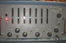
The old displays I remember were as shown below.
..... and keeping a drawer of good ol' #47 bulbs were always handy.
-RM
Who owns the IP?send me a sketch of the way or ways you think it can be done best and I will take it to loudspeaker company to see if they will try it and make prototype for me/us to play with.
THx-RNMarsh
jn
Edit: Hi Scott, we're just programmed to think in x 1/2 digits. The newer meters can be x 1/4 digits and probably others now.
I wonder who was the first to realize how annoying it was to trim a 10V reference as the meter auto-scaled back and forth.
I got an Easter egg from our HP sales rep to turn off an auto-cal feature that was annoying but was needed to guarantee the catalog specs. They had a 20Hz plus RF spectrum analyzer that you could fool into doing Dick Heyser's TDS measurements but the sweep time got so long that it forced an auto-cal in the middle.
Last edited:
Hi Scott,
Yes, the auto-cal cycle is a known since earlier HP days. As long as the temperature doesn't shift much in the instrument, the auto-cal isn't as necessary as it normally is. The same tactic is used to increase DMM throughputs and it can make a huge difference in throughput. If you are running the instrument under computer control, you can turn the auto-cal off, but force one after your measurement cycle completes. That way you still benefit from the auto-cal, but it doesn't affect your measurements.
I'm actually using my HP 3585A right now and it will execute a calibration sequence in the middle of what I'm doing now and then, but in my application it doesn't matter.
I don't know what voltage level your reference is, but I do know that a lot more things are calibrated during the calibration cycle but not the reference. There are a lot of offsets corrected, and the voltage levels are probably compared to the internal reference, but it doesn't get adjusted as it is the primary reference in your instrument.
I think it's amazing that this test equipment can even "auto-cal" to begin with.
-Chris
It would be good if the manu has experience with laminating of .5mm thick steel such as ThyssenKrupp Powercore 1200-100A, as well as using Stabolit 70 organic bonding lacquer. A process will be needed to bond the laminations such that the packing density is roughly 98%. That way, the permeability normal to the laminations is controlled. Since we do not care about azimuthal uniformity too much, grain orientation of the laminations will be unimportant.
Field contouring will require drilling holes to various depths and patterns, a better method than stamping plates differently prior to bonding, and easier than milling the gap surface profiles.
The manu will need FEA capability to determine the reluctance profile of the stack, and I suspect the pole tip stack will be different from the outer plate stack.
jn
Field contouring will require drilling holes to various depths and patterns, a better method than stamping plates differently prior to bonding, and easier than milling the gap surface profiles.
Sounds something like making transformer cores, or electric motor armature poles. That kind of thing.
Does drilling a lot of holes have the effect of creating conductive paths between laminations (maybe due to burrs or deformations left from drilling)?
I even had a piece of NLS test equipment.
These are way cool, surely someone has made them more recently,
with laser etching, and LEDs instead of incandescent lamps.
Last edited:
The old displays I remember were as shown below.
Yes, we had one of those at the university.
Sounds something like making transformer cores, or electric motor armature poles. That kind of thing.
Does drilling a lot of holes have the effect of creating conductive paths between laminations (maybe due to burrs or deformations left from drilling)?
You are dead nuts on the money with your thinking.
For the outer laminated structure, holes drilled to modify reluctance will be at the outer edges of the plate, at a sufficient distance that plate to plate conductivity is unimportant and eddies will not come into play.. That way, the inner gap surface is unmolested.
The alternative is of course to simply stamp or drill the plates prior to bonding. Again, rotation is unimportant as azimuthal field quality is not of concern. Stamping can simply cut away material at the edge in v notches, with higher reluctance plates having more v notches and less contact surface for the ID of the return iron cylinder.
For the front plate, the flux enters via the edges of the lams. The purpose in drilling holes is to build in "resistors" of various values to each plate depending on how the gap flux uniformity is. Instead of removing material on the ID of any specific plate, just drill holes at the outer edge. Because there is gapping between the plates due to the glue, the plates will tend to not share flux as much, so gap field tailoring can be done at the plate edges.
The outer cylinder, I'd make the bore perhaps a mil or two interference fit to the front plate stack, put the stack in liquid nitrogen, the use a shop press to quickly push it in. As they equilize, the stack will become fixed in place. Alternatively, it could be two piece.
Same with pole piece, but cool the pole iron and heat the gap lams. Both ends can be done separately.
jn
Last edited:
Who owns the IP?
jn
You, if you take care to. But if spelled out here in DIY … its public domain.
-RM
Since this is DIY, the laminations can be epoxied together using glasscloth as the spacer. That way, selection of the cloth weight will determine the spacing between plates. It is easy enough to get spacing in the 5 to 10% range of the plate thicknesses. I'd just use west epoxy with the tropical hardener (105 and 205 IIRC).
jn
IP...IIRC, when talks are given at conferences, there was a 6 month extension for filing patents...
This is a conference, right??
jn
IP...IIRC, when talks are given at conferences, there was a 6 month extension for filing patents...
This is a conference, right??
It used to be 1 yr. but 6 months is a safe bet. You should apply for provisional patent to hold your place. Be somewhat broad.... there may be 10 ways to mfr it … each a patent. Or cover as many ways to do the general idea as possible.
Do the holes drilled increase the impedance around the holes … eddy current around the holes? Explain in more detail, pls.
-RM
Do the holes drilled increase the impedance around the holes … eddy current around the holes? Explain in more detail, pls.
-RM
Last edited:
The holes are being used to decrease the overall permeability. Drill them away from the gap. So if you were making a 4 inch diameter vc, use say 8 inch diameter discs, and limit the holes to the outer half inch. The flux of the vc would be 1.5 inches away from any holes.It used to be 1 yr. but 6 months is a safe bet. You should apply for provisional patent to hold your place. Be somewhat broad.... there may be 10 ways to mfr it … each a patent. Or cover as many ways to do the general idea as possible.
Do the holes drilled increase the impedance around the holes … eddy current around the holes? Explain in more detail, pls.
-RM
hmmm, I suspect that the wire edm step that follows is probably not DIY though...🙁
jn
Wrong, conferences have restricted audiences. The provisional is so cheap and DIY I don't see why you would not just do that. If you have enough done to present a credible paper at a conference it is more than enough for one. The fee is $130 even an expensive lawyer would only charge $2000 or so to type out the form and mail it in. You still would have the issue that within one year you have to file and if you include international coverage it's a huge expense.This is a conference, right??
http://www.bobharter.com/provisional.pdf
Last edited:
 .
.- Status
- Not open for further replies.
- Home
- Member Areas
- The Lounge
- John Curl's Blowtorch preamplifier part III