Pavel, this is not a single tone methinks. The on off points are impulses.
Sure, it has infinite spectrum. Bursts are rather meant to move operating points due to thermal transients, mostly in the power stage.
My idea is to discuss test signals for amplifiers. Anyone interested?
My idea is to discuss test signals for amplifiers. Anyone interested?
Yes. How about including how we test for RF sensitivity, and power line sensitivity? IME, there is sometimes more going on in real world situations than we may be thinking about.
Last edited:
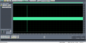
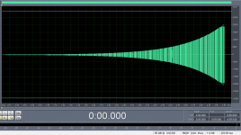
My idea is to have a test signal at low level (-20dBFS), total length of some 25s, which is at one moment changed to high level (-1dBFS) of short duration (now 50ms, to be tuned). This would make a short term thermal transient. Distortion of the low level signal would be measured and examined if it changes with time after the high level is turned off. There would be enough time for FFT. The envelope would look like this:
(Edit: RFI test is possible as well).
(Edit: RFI test is possible as well).
Attachments
Why don't all DC coupled, IC based linestages sound the same @ bass frequencues?
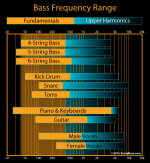
DC coupled (DC servo) linestages made with high gain (Avol > 100 dB) ICs, have enormous amounts of gain at bass frequencies (<= 220 Hz). So they have enormous amounts of feedback. So, you would expect, they would have vanishingly low distortion at bass frequencies. So, you would expect, they would all sound the same.
However, experienced listeners report that some of these devices sound better than others, in the bass frequencies. A lot better, in some cases.
Why?
My idea is to have a test signal at low level (-20dBFS), total length of some 25s, which is at one moment changed to high level (-1dBFS) of short duration (now 50ms, to be tuned). This would make a short term thermal transient. Distortion of the low level signal would be measured and examined if it changes with time after the high level is turned off. There would be enough time for FFT. The envelope would look like this:
(Edit: RFI test is possible as well).
I really like where you are going with this thought...
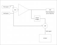
How about feeding the low level signal into a summing block to the amp, and also feeding the low level into a differential subtractor of the amplifier output, heavily into null. The high power tone gets injected only into the amp, and the amp output goes through a bridge limiter to prevent saturation effects into the differential circuit. block diag to follow...
I see you noted below as I was drawing...here is my thinking for others..the diode bridge is a very very fast limiter, sometimes used as a gating circuit...if anybody wishes, I can draw it up. one of it's advantages was to prevent scope input overload, as some circuits take time to recover from excessive input transients. I first saw it on a high speed sampling scope, it was used as a sample gate.
Note I also mentioned pure resistive and pure inductive loads. That allows selection of quadrants 1/3 alone, or operation through all 4 quadrants, where dissipation is significantly different.
Jn
Attachments
Last edited:

Would there be any benefit to using different frequencies for the low-level signal and the high-level burst? Say a 1KHz -20dB tone, and short bursts of -1dB at 100Hz, or for something really odd high-level burst of high frequency like 10KHz. I guess if the two signals were not harmonically related that would be better, as one could better "see" the HD of the low-level signal despite the high-level "noise".My idea is to have a test signal at low level (-20dBFS), total length of some 25s, which is at one moment changed to high level (-1dBFS) of short duration (now 50ms, to be tuned). This would make a short term thermal transient. Distortion of the low level signal would be measured and examined if it changes with time after the high level is turned off. There would be enough time for FFT. The envelope would look like this:
(Edit: RFI test is possible as well).
DC coupled (DC servo) linestages made with high gain (Avol > 100 dB) ICs, have enormous amounts of gain at bass frequencies (<= 220 Hz). So they have enormous amounts of feedback. So, you would expect, they would have vanishingly low distortion at bass frequencies. So, you would expect, they would all sound the same.
However, experienced listeners report that some of these devices sound better than others, in the bass frequencies. A lot better, in some cases.
Why?
If we start talking about things like that it would likely rekindle the Never Ending Argument. Throw gasoline on it, might be more a more apt analogy.
I suspect that the real problem with bass differences is what coupling caps are used, or the performance of the servo. I certainly believe in subjective differences in the bass. We have also found that the power supply 'capacity' seems to make a real difference also. Why, I don't know for sure.
How about different LF responses of different circuit schemes to different asymmetric waves.
Maybe. Depends on circuit design, IMO. I am quite sure that some designs will be immune to almost any signal ratios and the other ones might be quite sensitive.
Would there be any benefit to using different frequencies for the low-level signal and the high-level burst? Say a 1KHz -20dB tone, and short bursts of -1dB at 100Hz, or for something really odd high-level burst of high frequency like 10KHz. I guess if the two signals were not harmonically related that would be better, as one could better "see" the HD of the low-level signal despite the high-level "noise".
Maybe. Depends on circuit design, IMO. I am quite sure that some designs will be immune to almost any signal ratios and the other ones might be quite sensitive.
.....However, experienced listeners report that some of these devices sound better than others, in the bass frequencies. A lot better, in some cases.
Why?
I certainly believe in subjective differences in the bass. We have also found that the power supply 'capacity' seems to make a real difference also. Why, I don't know for sure.

I borrowed one of these Geoclense units from a friend of a friend. The intended purpose is to 'harmonise' the radiations from household wiring. Turns out when plugged into dual wall socket supplying any audio gear the sound changes with marked (resonant) increase in bass. Just sayin'.
Dan.
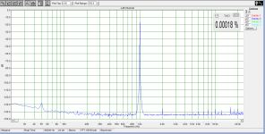
So nothing, yet. A "steady state" or suddenly changing in level and duration makes no difference. Negligible. Frankly, I was expecting this a bit. Maybe some non FB circuit might show some changes with these "non steady state" signals. It also indicate that complaints to so called "steady state sine wave tests" are in most cases based on no evidence, just on "feelings" and opinions. I also used a notch filter to magnify the residual, again, nothing. All negligible, only notch filter settling. No changes in harmonic profile and amplitudes.
Last edited:
DC coupled or DC servo? Not the same thing. A DC servo implements AC coupling in a more complicated way than simply using a coupling cap, so there could be differences in LF rolloff, which may be audible.DC coupled (DC servo) linestages made with high gain (Avol > 100 dB) ICs, have enormous amounts of gain at bass frequencies (<= 220 Hz). So they have enormous amounts of feedback. So, you would expect, they would have vanishingly low distortion at bass frequencies. So, you would expect, they would all sound the same.
However, experienced listeners report that some of these devices sound better than others, in the bass frequencies. A lot better, in some cases.
Why?
Pavel, IMO the duration of the full level signal is much too short. To reproduce music conditions a say 500mS burst (or longer) of full scale low frequency (40Hz ?) followed by the low level signal (-40dB ? ) would be more appropriate to reveal signal related noise floor changes. Also a 'lousy' consumer amplifier would be more appropriate than a good/high quality amp.Hi Jn, I understand your suggestion, possibly I may try it as well, after some circuit preparation.
Dan.
Attachments
DC coupled (DC servo) linestages made with high gain (Avol > 100 dB) ICs, have enormous amounts of gain at bass frequencies (<= 220 Hz). So they have enormous amounts of feedback. So, you would expect, they would have vanishingly low distortion at bass frequencies. So, you would expect, they would all sound the same.
However, experienced listeners report that some of these devices sound better than others, in the bass frequencies. A lot better, in some cases.
Why?
Short answer is: because listeners do not listen to sound quality that sufficiently represented by what you measure. 😉
Loop gain at LF is irrelevant. It is relevant for HF.
Do you mean fundamental note when you say bass frequencies, or, what percentage of bass are actually higher frequencies?DC coupled (DC servo) linestages made with high gain (Avol > 100 dB) ICs, have enormous amounts of gain at bass frequencies (<= 220 Hz). So they have enormous amounts of feedback. So, you would expect, they would have vanishingly low distortion at bass frequencies. So, you would expect, they would all sound the same.
However, experienced listeners report that some of these devices sound better than others, in the bass frequencies. A lot better, in some cases.
Why?
(edit:added image, changed few words for clarity.)
Attachments
Last edited:
Pavel, IMO the duration of the full level signal is much too short. To reproduce music conditions a say 500mS burst (or longer) of full scale low frequency (40Hz ?) followed by the low level signal (-40dB ? ) would be more appropriate to reveal signal related noise floor changes. Also a 'lousy' consumer amplifier would be more appropriate than a good/high quality amp.
Dan.
Dan,
Don't forget PMA's FFT averages out noise, so no visible change would be expected if there were only a brief noise increase following a transient. The test that was shown was a test for nonlinear distortion of the input signal.
If there were a transient induced input signal distortion effect it would be weighted in the FFT according to its time duration relative to the FFT acquisition time.
Last edited:
Geoclense Just sayin'.
Bioplasmic Radiation (Human Generated) imprinting produced by…
Juvenile emotional stress
Illnesses and diseased organs
Death imprints/” Paranormal” Activity
Previous occupants’ emotional distress
Negative psychic impressions/Psychic attacks
Solar and Planetary Radiation imprinting produced by…
Planetary Retrograde influences
Beta Gamma from X, C & M-class Solar Flares/Solar Winds
Beta Gamma Radiation from Cygnus X3 for people in the Northern Hemisphere
At least you don't have to worry about the last one 🙄
Reading through the whole thing, stunning in fact almost worth the $99 to take one and show that there is probably nothing inside it.
Last edited:
Planetary Retrograde influences
Pls PM me your natal chart
😀
George
Pavel, IMO the duration of the full level signal is much too short. To reproduce music conditions a say 500mS burst (or longer) of full scale low frequency (40Hz ?) followed by the low level signal (-40dB ? ) would be more appropriate to reveal signal related noise floor changes. Also a 'lousy' consumer amplifier would be more appropriate than a good/high quality amp.
Dan.
I tried all possible and impossible combinations of amplitudes (from noise to full scale), lengths (hundreds of ms to tens of s), signal/space (noise) transitions etc. Nothing interesting is happening, the "non-steady state" signals give the same results as "steady state" signals. No problems with sudden change of amplitude. Much more severe conditions than with any kind of natural music signal. Nuts.
I do not have any "lousy" consumer amplifier here, mine are rather overdimensioned in heatsink capacity, so they have no thermal issues under any signal conditions. If the amp had problems with dynamics, I would probably recommend to throw it away.
This is one of the signals.
Attachments
- Status
- Not open for further replies.
- Home
- Member Areas
- The Lounge
- John Curl's Blowtorch preamplifier part III