<Very complete precis clipped cause you've already read it.> Thank you very much for taking so much time to detail your evil plan to rule the world from your hollow volcano. Count me in.
Haven't even a tiny clue, but will be enjoying the journey immensely.
Much thanks, as always
Chris
And that is only the first section in the analysis, the part I would consider bog standard. As I mentioned to Demian, I've no clear engineered approach yet for actually measuring the non linear time variant full frequency span impedance variations on a fully hard music driven device..that is where the real brainstorming is needed. Sine waves need not apply.
Haven't even a tiny clue, but will be enjoying the journey immensely.
Much thanks, as always
Chris
Last edited:
Ah yah, current research.They're getting closer to room temp these days, Bybee et al will leave out the giga Pascals of pressure needed, details, details.
All those guys come around, give talks and senimars, present results.
I honestly believe they get paid to write a lecture abstract that absolutely no human can possibly understand. My writings are T-ball in comparison to their World Series abstracts. I swear the only reason for their abstracts is to use it as a blunt instrument.
Jn
We still need a tongue in cheek (TIC) emoticon
What we also need is reinstating the BS flag emoticon. It was removed 10 years ago, after some sensitive souls complained of me abusing it.
Ah yah, current research.
All those guys come around, give talks and senimars, present results.
You mean you're not impressed with a one micron square mono-atomic layer in a diamond vice? How do they instrument measurements on this stuff?
The "magic angle" graphene stuff is actually seriously interesting.
....I think of it as two regions of operation, the audio range up to 100K, and the RF region above 100K.
In fact, it might be a good idea to resistively load a cable at the loudspeaker end with either the series RC or just the R, as suggested by Dan.
Yes and so do I, always have.
Up to say 100kHz or so a decent/good amp should be able to cope with and actively damp/dump/quench return energies.
Above say 100kHz or so the line is effectively unterminated at both ends and so is prone to RF pickup, RF resonances and the possible consequences.
In practice I find all systems subjectively clarify significantly and usefully with the addition of less than a dollars worth of resistors.
Yes, I consider adding such termination resistors at both cable ends as mandatory now that I know the subjective difference.After all most speaker cables are picking up RF from the air as well. It makes sense to DAMP the RF resonances with a resistor of reasonable value, like 75-120 ohms, depending on the cable.
CF, MF and WW all cause different sounds and at normal/background levels 0.6W MF is high enough power rating to not smoke !.
Surprisingly just a parallel pair of MF 150R 0.6W at each cable end is enough to cope with 100W rated amp running flat out on variety of programme, go figure.
Dan.
Originally Posted by RNMarsh View Post
So. is the back/counter emf from the loudspeaker reduced if I place a low value resister at the speaker (across it)? Not an RC network.... just an R.
And, 2; By reducing the range of Z variation as a load on the PA, is this audible with some amp topologies more than others'?
I run 75R at each end of 75R coax speaker cable.....adding these resistors is easily audible, removes hf dirt.
Dan.
I use a lower value .... closer to 50 or even lower.... power resistor across the speaker term. at the speaker. Demian and I added such a R at one end of Monster Cables' higher-end cable and sold it without anyone knowing it was there --- covered by the metal end term. sleeve. About 15-20 years ago now.
But I did it to reduce the Z variation to the PA and make it more constant and R. Nothing at all to with transmission lines et al. Seems to make a difference. I even tried 8 Ohm across speaker and it just gets better but wasteful.
Its easy to try it for most people.
So, I am still wondering if anyone else has an explaination beside a more constant R for load to PA..... counter-emf changes..... and .....??
THx-RNMarsh
Last edited:
I'm fine, you guys don't get it that the one speaker in reverse phase condition is only for testing/decision phase.Yes, of course, more to the point, does Dan get it, or is he hopelessly lost?
Once decision is made on correct or subjectively best polarity both speakers are set to this polarity condition.
I stated this in my posts and used the term decision, perhaps you and DF96 et al missed that bit.
I try to help/explain, you misread/misunderstand and then you heckle and then because you have the story wrong you continue to heckle and incite others to join in because you have the story wrong and so it goes.....like really ?.
I suspect I'm better grounded than the lot of you hecklers......if nothing else I make sure to walk bare footed whilst taking the household pair of mutts for a walk/sniff etc at the huge local nature reserve/sports grounds twice daily.I suspect he is pleasurably lost in space... 🙂
His Goop may contravene several intoxication laws 🙂
I feel privileged indeed to be able to explore and experience such a clean quiet and peaceful environment only a few kilometers from the shore line of thousands of kilometers of unpopulated and clean southern oceans and breathe the pristine air.
Probably 300+ days a year I can have front and/or rear doors open and let sunshine, natural heat and clean air and external sounds in all day long.
This means I am hearing lots of outdoor natural sounds which keeps my hearing calibrated to 'nature' default setting, and not habituating to 'man made' sounds and environment sounds.
So what kind of contact do you guys have with nature, and what are your work and home environments like etc ?.
I mean this in interest and not in challenge, perhaps environments affect ones senses in different ways ?.
Dan.
Last edited:
Don't mention the speaker 😉😀To do listening tests, I think you'd need a buffer amplifier with (high power) adjustable
purely resistive input impedance, between the load end of the speaker wires and the speaker.
There are too many variables introduced by the speaker to allow that to enter the fray.
Then experiment for audible differences with matched vs unmatched loading on the wires.
I get it, I'm saying it's uselessI'm fine, you guys don't get it that the one speaker in reverse phase condition is only for testing/decision phase.
Once decision is made on correct or subjectively best polarity both speakers are set to this polarity condition.
He did so using his learnings (which I also learned) in regard to sub wavelength t line analysis which was that it was taught as inappropriate. That teaching however, is a rule of thumb, not a rule of physics. At that time, T-line theory was taught for engineers to understand waveguides, t-lines, stub tuning, quarter wave transformers, neat stuff like that. Never was sub wavelength t-lines considered.
John, please let's not oversimplify. I have a problem with your statement "Never was sub wavelength t-lines considered.". Well, I do not think so. I am permanently repeating an example where t-line length is negligible compared to signal wave length and the example is 6km wave in a 6m cable. 6km wave is 50kHz, well about audio band. I would never say that 6m cable has no issues with MHz signals, though 6m wavelength is for 50MHz. I have plenty of measurements showing the problem with sub wavelength signals, however from some point they are negligible.
I will stop posting measurements in this thread. They need hours of preparations and no matter what is shown, someone else needs seconds to write his pseudo-theoretical arguing based just on his subjective hypothesis. This is a rule of thumb here. So maybe I may start my own thread and I would appreciate real arguments and real results then, or maybe I will not do it just considering it totally useless.
Your practical input is valued hereI will stop posting measurements in this thread. They need hours of preparations and no matter what is shown, someone else needs seconds to write his pseudo-theoretical arguing based just on his subjective hypothesis. This is a rule of thumb here. So maybe I may start my own thread and I would appreciate real arguments and real results then, or maybe I will not do it just considering it totally useless.
Re Bateman
http://www.waynekirkwood.com/images/pdf/Cyril_Bateman/Bateman_Speaker_Amp_Interaction.pdf
He says
This is the same as I do, I say the real difference would be in tens of ns and I say it is a no-issue, especially compared to all other flaws of the complete audio system.
http://www.waynekirkwood.com/images/pdf/Cyril_Bateman/Bateman_Speaker_Amp_Interaction.pdf
He says
Assuming our typical 4.9metre length cable, this two way transit time will approximate 50nS equivalent
to just 0.36° at 20kHz, or 0.018° at 1kHz.
This is the same as I do, I say the real difference would be in tens of ns and I say it is a no-issue, especially compared to all other flaws of the complete audio system.
He mentions the Maplin mosfet amps, I have a couple of those built in early 80's, still going strong after years of abuse including experimenting with 100%NFB 🙂
Is there a model name I could search or what were the reviewer and owner opinions ?. What type/power rating 50R did you use ?.I use a lower value .... closer to 50 or even lower.... power resistor across the speaker term. at the speaker. Demian and I added such a R at one end of Monster Cables' higher-end cable and sold it without anyone knowing it was there --- covered by the metal end term. sleeve. About 15-20 years ago now.
Easy doesn't mean that it's not easier to write and argue about it for some. IME I well agree loading R is subjectively cleaner/better than no loading R, but I was never convinced that shunt '8R/6R' is optimal, to me the result is overly/unnaturally damped besides the power wastage issues, I haven't tried values like 50R so.But I did it to reduce the Z variation to the PA and make it more constant and R. Nothing at all to with transmission lines et al. Seems to make a difference. I even tried 8 Ohm across speaker and it just gets better but wasteful. Its easy to try it for most people.
I still reckon a critical first thing to do is to damp/quench any induced energies that are on the antenna/speaker wire transmission line and this correctly matched loading needs to be purely resistive to be fully effective especially as we go into the age of ubiquitous micro wave and millimeter wave transmissions. Above 100kHz or so most single pair wires will be close to their rated nominal impedance and this is the optimal loading as I understand it and hear. Below 100kHz amplifiers need to be able to deal with load impedance variations and return energies, but not all amps are good in this aspect. Amplifier output coupling/matching networks (Zobel etc) also needs inspection....many amps are straight connection from the series output coil and no shunt components to deal with induced and reflected RF line energies. Loudspeaker internal impedance 'flattening' is another 'next step' and this fixes a bunch of below 100kHz issues.
Reader Digest Version, reactive loading causes harmonic currents which stir up first order noise mechanisms which get worsened/multiplied by further downstream noise mechanisms, quench the RF stuff and the audio band throughput will be cleaner.So, I am still wondering if anyone else has an explanation beside a more constant R for load to PA..... counter-emf changes..... and .....??
Dan.
Though I agree with his (Bateman) cable analysis (all of us can do it in Microcap or LTSpice and confirm his results, i.e. that unterminated speaker cable of std. length has issues above several MHz or say 1MHz), I have problems with the rest. His amplifier failure during the test might be just an issue of the design used. I use a non global NFB class A design for my tests.
The bursts seen in his scope screen he attributes to the cable, however I am not sure about it. I measure similar bursts on a regular basis and IME they are a result of power supplies function, both linear and SMPS. If I use an isolated supply for the generator and battery supply for my notebook and scope, all the bursts disappear.
I think all of such measurements must be repeated in another independent workplace. This would be a scientific method and then we may say something was proven. Up to this point, we have only just another hypothesis.
Is there a model name I could search or what were the reviewer and owner opinions ?.
What type/power rating 50R did you use ?
The cables were the M2.2 and M2.4. This was 1997 or 1998. We used a Caddock power film resistor, 100 Ohms. MP850 I think. It was imbedded in thermal epoxy inside the big aluminium shells even though it would never get stressed. Finding a review may be hard. Monster was not taken seriously in high end circles even then.
The rationale was that virtually all speakers are inductive at high frequencies (even electrostatic speakers). Terminating the cable at around its characteristic impedance (100 Ohms) would move that HF impedance back to a more normal Z and reduce/eliminate reflections at high frequencies as well as improve stability. it did seem to have the desired effect of a different (better) sound pretty much everywhere it was used. We can touch on the marketing side of that issue but its not nice to point out so much human frailty. . .
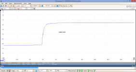
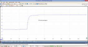
Just measured at speaker end behind 6m cable zip cord, speaker connected. Amplifier with Tr = 1us approx.
1) open end /speaker only/
2) 150 ohm termination added
There is almost no difference and also no cable reflections are seen in none of the measurements. Class A non global NFB amplifier. So, what is it really all about???
1) open end /speaker only/
2) 150 ohm termination added
There is almost no difference and also no cable reflections are seen in none of the measurements. Class A non global NFB amplifier. So, what is it really all about???
Attachments
Last edited:
With the greatest respect JN, I stand by my earlier assertion. I might be more convinced if I could see the cable behavior separated from the speaker load characteristics to judge the relative effects of each.
Secondly, but perhaps tangential to this discussion, it’s clear CB’s Blameless had stability problems.
Is anything above a few hundred kHz as important in Audio? If you are pumping stuff at MHz down a cable to a speaker load, you ‘get what you deserve’. But ok, here we are talking science and engineering, so in the spirit of investigation some of us do these things.
I suspect CB disabled the front end filter on his blameless to get the BW so the amp would probably have had overshoot problems and other issues at HF (with square wave testing). Unfortunately, CB does not go into detail so we will never know.
Speaker guys are mostly subjectivists. With speakers, where so many compromises are made, you cannot brag with how good it measures when everyone can hear clearly how bad it sounds. With amps, you can see so many that admit they cannot hear but are pretending that well measured amp sounds so great because they all do sound similar anyway. I think the objectivist of speaker world is Earl Geddes.
Patently untrue. Much progress has been made by real objectivists like Floyd Toole or Sean Olive. Just about everything can be measured of speakers, and these measurements correlate one on one with preceived qualities. There is no Voodoo left in loudspeaker development.
- Status
- Not open for further replies.
- Home
- Member Areas
- The Lounge
- John Curl's Blowtorch preamplifier part III