Archimago's Musings: MEASUREMENTS: Oppo BDP-105 RCA, XLR, HDMI, and other stuff for the record (like MQA CDs?!)... some more measurements, but still not the wideband noise you are looking for.
some more measurements, but still not the wideband noise you are looking for.
Hello Bill,
such measurements as I am looking for are not displayed very often, better say almost never.
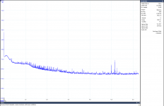
Just to show an example, let's see my measurement at the output of the Parasound Halo Integrated integrated amplifier, which was connected in a system with Denon SACD/CD player, but the volume knob at minimum. The whole chain powered from the power conditioner.
You can see my noise measurement up to 6MHz, Y axis is calibrated, in dBV, FFT conditions shown in a box at the right side.
This is a pretty good result above the audio band, but not so good in the audio band. This was confirmed by Stereophile test in
https://www.stereophile.com/content/parasound-halo-integrated-integrated-amplifier
by Atkinson's measurement of S/N.
Attachments
You can see my noise measurement up to 6MHz, Y axis is calibrated, in dBV, FFT conditions shown in a box at the right side.
This is a pretty good result above the audio band, but not so good in the audio band.
Could be, but measuring "noise" in dBV is incorrect and potentially irrelevant.
Well, regarding "noise", a qualified person like you can make calculations from bin width, sample frequency and no of samples stated in the graph. Calibration in dBV is good if you want to read amplitude of spikes, here near 5MHz. Or should it be uncalibrated? 😉
So Pavel, the question then becomes whether poor EMI/EMC design and testing is the cause of this. If so then maybe there is a market for a magic interconnect that actually does something useful in its black box. A 200kHz LPF on an amplifier input should in these cases improve things.
So Pavel, the question then becomes whether poor EMI/EMC design and testing is the cause of this. If so then maybe there is a market for a magic interconnect that actually does something useful in its black box. A 200kHz LPF on an amplifier input should in these cases improve things.
It is difficult to blame everything on poor EMC design. However, it may be a potential problem. So it is definitely better to have components with clean analog output and to use RC filters at the input. But, as you know, HF signals, especially very high frequencies, may bypass the RC filter in case of less than "good" design, and we know that audio components are almost always designed without taking RFI rules into account. For example, you may see a nice milled aluminum block but EMI/RFI is getting easily inside along the signal wires coupled through RCA connectors insulated from chassis.
As you know, we have 3 paths how the EMI/RFI/HF gets inside the audio circuit.
- with signal from the preceding component
- coupled through air into cables and poorly shielded circuits
- through power supply lines
So RC at the input is just only one of the things we need to take care about.
Of course. I really should sleep before I post 🙂. But you would agree that apart from Mr Flooby and his microsaturations even high end types tend to agree that a filtered IEC socket is a good thing? But audio interface filtering is masochistically ignored by some.
Archimago's Musings: MEASUREMENTS: Oppo BDP-105 RCA, XLR, HDMI, and other stuff for the record (like MQA CDs?!)... some more measurements, but still not the wideband noise you are looking for.
These guys are pretty good.
See also more MQA deliberations:
Archimago's Musings: COMPARISON: MQA "Authentication" & Sound Quality? (Mytek Brooklyn & Meridian Explorer2)
"And yes, no need to mince words. MQA is a form of DRM which not only insults end users, but also pisses off manufacturers. Linn is right IMO to call it an "outright land grab".".
It is a serious read, so if you only want to spend 30 seconds to get the lowdown about MQA, don't bother.
Jan
As a few other more prominent audio engineers have stated, given the liberal use of compression and filling 8 bits of resolution with data noise, I agree MQA is MP3 for HD.
The only claimed sonic improvement over conventional linear PCM and filters is it's timing accuracy and claimed lack of time smear, but based on the opinion of several superb engineers who understand the issue better than I, the claimed filter topology does not explain it. In the absence of any additional information about this, the "time accuracy enhancement" could be some form of transient-enhancement processing, which makes it an effect, not accuracy enhancement.
Once again, I have been scouring released information regarding MQA and nothing else has been revealed AFAK. The targeted appeal to IP owners has been well established, but fidelity has not been, in the most literal use of the word.
Cheers,
Howie
Of course. I really should sleep before I post 🙂. But you would agree that apart from Mr Flooby and his microsaturations even high end types tend to agree that a filtered IEC socket is a good thing? But audio interface filtering is masochistically ignored by some.
Removing RF from incoming AC is a good thing, but many IEC AC inlets can capacitively bypass RF to the chassis. In a correctly designed system (all components considered) this is correct methodology, but in consumer audio with pin 1 issues and/or unbalanced RCA interconnects and incorrect signal grounding topology this can lead to that RF flowing between components and modulating the audio. PMA has a lot of experience in this area. In Linear Audio Vol. 5 there is an excellent article by Bruno Putzeys titled: Get your audio off the ground" which addresses many of these issues.
Cheers,
Howie
My experience with cap filters on AC input is that they couple both line energy and RF into the AC ground. If that AC ground is shared with audio (normal practice) and another box is similarly connected then any differences in the ground potentials are shared across any connections between the boxes. even in balanced systems that's not a good think and in normal audio connections even microamps of leakage can become the dominant noise source in otherwise exceptional designs.
I would rather see well executed doubled insulated (Class II https://en.wikipedia.org/wiki/Appliance_classes) power supply designs that don't need a ground than filtered IEC connections. Most of those filters are actually designed to keep supply and circuit noise inside the box, not prevent ingress.
I would rather see well executed doubled insulated (Class II https://en.wikipedia.org/wiki/Appliance_classes) power supply designs that don't need a ground than filtered IEC connections. Most of those filters are actually designed to keep supply and circuit noise inside the box, not prevent ingress.
Demian I think that a good double insulated system would indeed solve many grounding problems. My experience with CE and other EMI testing is that the filters are indeed designed to keep enough in the box to pass testing. It is much better to not make the noise in the first place or kill it at the source. A hard ground does look good for liability and insurance purposes though.
Removing RF from incoming AC is a good thing, but many IEC AC inlets can capacitively bypass RF to the chassis. In a correctly designed system (all components considered) this is correct methodology, but in consumer audio with pin 1 issues and/or unbalanced RCA interconnects and incorrect signal grounding topology this can lead to that RF flowing between components and modulating the audio.
Yes. And the issues are with single-ended interconnections as well, even higher than the "pin1" issue.
As the guys have said before me, the best way to prevent this would be isolating transformers with minimum primary/secondary capacitance, because even class II with "standard" transformers is not a solution, due to high capacitances and "floating" has its own issues then.
the best way to prevent this would be isolating transformers with minimum primary/secondary capacitance
Wouldn't you get greater isolation, at lower cost, by connecting two low-cost isolation transformers in series (achieving isolation-squared), rather than one super duper, medical grade, femtofarad-coupling, isolation transformer?
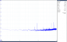
This is what we usually get at the output of an audio preamplifier, which is not connected to anything but a measuring instrument (battery operated) and the preamplifier is supplied from a standard stabilized power supply inside Al metal box. Class II. Quite a lot space for improvements, right?
Attachments
Pavel, just out of curiosity, are you in the country outside of Prague or closer to downtown? That's a good bit of HF hash.
Pavel, just out of curiosity, are you in the country outside of Prague or closer to downtown? That's a good bit of HF hash.
I am about 5km from downtown.
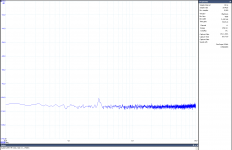
But the EMI sensitivity issue can be solved, as in this measurement shown. Now, the link stage has separate power supply and is built in well-shielded box, input RCA jacks are mount directly to the chassis and shortest cables (few cm) inside the box are used. Still something around 300kHz.
Attachments
Thanks Pavel, since you're so close to downtown, I'm coming to visit! 😉
Well-shielded box meaning essentially sheet steel, and not something like the beautiful milled steel preamp boxes that Gerhard has shown for some of his <1 nV preamps?
Well-shielded box meaning essentially sheet steel, and not something like the beautiful milled steel preamp boxes that Gerhard has shown for some of his <1 nV preamps?
Daniel, you are always welcome here 🙂. The box is standard industrial box with Al sheets, not that sophisticated as the one you mentioned.
Well, regarding "noise", a qualified person like you can make calculations from bin width, sample frequency and no of samples stated in the graph. Calibration in dBV is good if you want to read amplitude of spikes, here near 5MHz. Or should it be uncalibrated? 😉
That would be pretty hard from a chart, anyway, "spikes" will be shown on a noise spectral density scale as well. And BTW, the spectral noise density doesn't have spikes, those are statistically correlated spectral components.
The problem is, such a representation in dbV vs. F is not a correct metric of the "spikes" amplitude vs. the noise amplitude. Assuming they fall within a bin, "spikes" have a constant amplitude, disregarding the bin size, while the noise amplitude depends on the bin size.
But it does qualitatively illustrate what you mean.
- Status
- Not open for further replies.
- Home
- Member Areas
- The Lounge
- John Curl's Blowtorch preamplifier part II