I remember the LH0063 in a TO-3. The datasheet listed the little brother device LH0033 in a G12B metal can, and the LH0063 in a TO-3, asAnyone remember the Burr-Brown modified TO-3 package buffer, the 3553? I see someone wants 200 US for one.
Fast, and Damn Fast Buffers.
Sadly the datasheets that survived into the internet era, were scrubbed of this little piece of amusement.
edit- google searching for snoa725a takes you to app note 227 which discusses these (sans "Damn Fast")
Last edited:
Anyone remember the Burr-Brown modified TO-3 package buffer, the 3553? I see someone wants 200 US for one.
I think I have one of these somewhere, several folks made them, power op-amps and power buffers for a period when folks paid $$$ for them. I posted pictures and schematics here a couple of years ago ironically most of the discrete chips that went into them are still around.
Anyone remember the Burr-Brown modified TO-3 package buffer, the 3553? I see someone wants 200 US for one.
Scammer, it's $55 on Amazon https://www.amazon.com/Burr-Brown-3...dp/B00E9H2MYW?ie=UTF8&*Version*=1&*entries*=0
Sadly the datasheets that survived into the internet era, were scrubbed of this little piece of amusement.
I guess Pease's jokes went with him.
I wonder what the PJFETs in them were?I think I have one of these somewhere, several folks made them, power op-amps and power buffers for a period when folks paid $$$ for them. I posted pictures and schematics here a couple of years ago ironically most of the discrete chips that went into them are still around.
I wonder what the PJFETs in them were?
I'm afraid I've probably tossed this stuff out. I don't recall there being PJFET's in the BB parts. The inputs were N diff-pairs IIRC (2N5xxx from Siliconix).
EDIT -Sorry I was thinking of the op-amps. Siliconix did have PFET singles in their catalog but I would have to find it to see if there were duals. Micropower and Siliconix regularly offered matched singles in waffle packs though.
Last edited:
C'mon guys.
For line level stuff you need only TWO transistors and two diodes, or three transistors and no diodes plus an opamp to create a class A buffer with or without gain. A single resistor from the opamp output to the buffer output bootstraps the opamp into class A. Suitable SOT223 devices cost ~50c or so.
I published a circuit with measurements in low single digit ppm in 2009 on this. 10V pk into 200 Ohms at < 10ppm at 20 kHz, and ~2-3ppm into 600 Ohms. measured on an AP - sims said ppb.
(and no Waly, I am not 'promoting' myself here, just pointing out that there's no need to overcomplicate things)
Last edited:
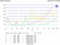
Attached is a plot of a string of twenty 2 ohm resistors fed via a 1,000 ohm unit. The frequency response is measured at each tap. The parts were on a solderless breadboard.
The second plot is a single 2 ohm resistor just clipped to the 1,000 ohm unit.
Hi Ed
What do you want to show with these plots?
If I understand, the Y axis is the voltage drop across the resistors strip. It seems you are using a 3V source.
The increase in voltage drop at higher frequencies seems to be due to the inductance of the strip construction (*)
The difference btn the lowest cyan line (2 Ohm tap) of att.1 and the single line (single 2 Ohm resistor) of att.2 confirm this.
(*)it shows as a lot of inductance (~10 -15mH ?)
George
(and no Waly, I am not 'promoting' myself here
Yes you do, but if you ever used a proper instrument to measure your stuff, then you are excused. I'm sick of people promoting simulations as absolute truth, as much as of people measuring ultra precision stuff on solderless breadboards and then claiming a new breed of physics.
Waly. If you look it says measured on an Audio Precision to that value even though simulation showed much lower. Bonsai is no slouch and has real world experience with real products and real measurements. Just saying.
Hi Ed
What do you want to show with these plots?
If I understand, the Y axis is the voltage drop across the resistors strip. It seems you are using a 3V source.
The increase in voltage drop at higher frequencies seems to be due to the inductance of the strip construction (*)
The difference btn the lowest cyan line (2 Ohm tap) of att.1 and the single line (single 2 Ohm resistor) of att.2 confirm this.
(*)it shows as a lot of inductance (~10 -15mH ?)
George
George,
What I think I am showing is how bad the solderless breadboard actually is! If it can ruin test results with an impedance of 2 ohms, it has to be horrible. I read the increase level at HF as leakage capacitance.
Using as few and hanging in the air connections I got the much better results as shown. I did drop the input voltage from 5 to 1.25 volts peak.
Attached is the final results of a three way loudspeaker with base line graphs of 4, 8, 12, 16,... resistors without the breadboard.
Attachments
for that matter clever technique can wring a lot out of better < k$ soundcards like the ESI Juli@If you look it says measured on an Audio Precision...
it is more tedious to get good results compared to dedicated equipment like AP - but its also unlikely to err on the "too good to be true" side - more likely to hit equipment limitation with a soundcard
We had two AP's in the Tokyo lab - I used the SYS2722 (I think that's the model name) to do the measurements on the buffer.
http://hifisonix.com/wordpress/wp-c...niversal-Small-Signal-Class-A-Buffer-V1.0.pdf
Interestingly, there was a big clear-out of the lab and a lot of gear that was fully depreciated was scrapped off. I got a great 200 MHz Philips analog scope (which was completely destroyed last year by the shippers en-route from Taiwan to the UK - another interesting story).
Well, back to the Tokyo story: I ran like hell up the stairs to the lab, my heart set on the old AP which still worked perfectly. Some other guy got there first unfortunately. Philips was a big player in CD's, Amps (Marantz, Automotive, Consumer class D etc) so the place was well set up. Stax headphones etc
I'm using a Focusrite Scarlett Solo now - with some preconditioning gain its good for about 6 or 7 ppm.
Last edited:
George,
What I think I am showing is how bad the solderless breadboard actually is!.
And give Ed the 'No Sh*t Sherlock award of the day' 🙂. I had a bit of that aged about 14. Never touched it again and no interest in doing so. Horrid stuff.
Slabs of pain.And give Ed the 'No Sh*t Sherlock award of the day' 🙂. I had a bit of that aged about 14. Never touched it again and no interest in doing so. Horrid stuff.
Well, back to the Tokyo story: I ran like hell up the stairs to the lab, my heart set on the old AP which still worked perfectly. Some other guy got there first unfortunately. Philips was a big player in CD's, Amps (Marantz, Automotive, Consumer class D etc) so the place was well set up. Stax headphones etc
The moral I'm taking away from this is keep up my exercise regime. 😀
Ugh on the scope, nor am I surprised by the buffer's performance. The LM4562 is stupid good and a tidy little bit of discrete buffer oomph isn't going sully that too much.
for that matter clever technique can wring a lot out of better < k$ soundcards like the ESI Juli@
Hasn't this always been the way tho? The clever guys can wrangle the test equipment and more importantly understand what they are looking at*. Maybe the AP made people lazy.
*Does not apply to me. Forgotten it all.
- Status
- Not open for further replies.
- Home
- Member Areas
- The Lounge
- John Curl's Blowtorch preamplifier part II