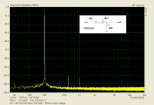
OK. This result, with 2 back-to-back tantalum capacitors is from standard use as a coupling capacitor. Reminder - my method is at the limit. Is 0.00047% too much? Do you want different load, THD vs. frequency plot, test place photo?
Attachments
Last edited:
I just repeated my 32 year old test with the same tant cap values and the same test conditions. Inverse parallel was about 15dB BETTER than the same parts in series. 20db better compared with a single 4.7uf tantalum cap. Perhaps my test conditions encouraged this result, but I don't see how. What SY measured, I cannot answer for.
When you put them in anti-parallel, the equivalent capacitance is 4 times than when they are placed in series. So the test voltage across the cap is 4 times smaller. I would expect that it indeed drastically lowers distortion.
Four times lower is 12dB less.
Jan
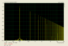
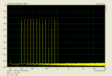
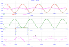
More with tantalum 4u7 - 4u7 back-to-back. Triangle (4.40 Vp-p) and multitone.
P.S.: The part under test is 4.7uF/6.3V
The further test with a single part has shown no worsening in distortion.
P.S.: The part under test is 4.7uF/6.3V
The further test with a single part has shown no worsening in distortion.
Attachments
Last edited:
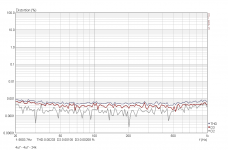
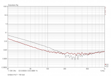
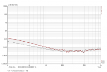
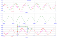
All else same, load changed to 1k5 and only one tantalum capacitor 4u7. High pass filter with 23Hz -3dB frequency corner. Yes, now we can see something. But everyone would make a LF corner somewhere at 1Hz - 2Hz, and then, no distortion even with tantalum. Myth disproved. Parallel x series explained by Jan.
P.S.: comparison with 2 x 4u7 back-to-back added. See H2 reduction.
P.S.: comparison with 2 x 4u7 back-to-back added. See H2 reduction.
Attachments
Last edited:
My test voltage was 3V rms.
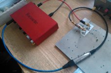
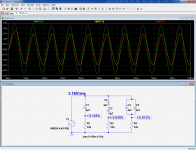
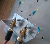
I was curious enough to make the test myself; see pics for exact conditions & voltages across the caps.
To my surprise, in those conditions, the anti-parallel version comes out better.
Tantalums were 4µ7/35V, hermetic metal case
Attachments
To my surprise, in those conditions, the anti-parallel version comes out better.
4 x higher capacitance than for series connection. Already explained by Jan. (Change load to 82 ohm for parallel).
Last edited:
ITo my surprise, in those conditions, the anti-parallel version comes out better.
Of course it does, as predictable.
Can you try again by doubling the series caps and halving the // ones.
Jan
Look at the voltages across the individual caps they are practically identical for the series and anti-parallel cases. I have chosen the 330 ohm for precisely that reason.4 x higher capacitance than for series connection. Already explained by Jan. (Change load to 82 ohm for parallel).
Are you sure that your test equipment doesn't have an internal coupling capacitor: your measurements yield much lower absolute THD levels than mine anyway, and apart the fact that you used tantalum drops, there is no significant difference
I have resistor load made with a real component. 4 x higher capacitance makes 4 x less voltage across it.
You are showin a node voltage (resistor). Plot capacitor voltage, phase shifts make difference. No simple amplitude addition here.
You are showin a node voltage (resistor). Plot capacitor voltage, phase shifts make difference. No simple amplitude addition here.
Attachments
Last edited:
Look at the voltages across the individual caps they are practically identical for the series and anti-parallel cases.
How can that be - it appears to repeal Ohms' and a couple of other guys laws!
jan
He has to plot capacitor voltage (he plotted resistor voltage), he forgot about phase shifts, there is no simple amplitude addition.
NoYou are showin a node voltage (resistor).
That is exactly what I have done: Look at the pic: the voltages are not absolute, they are of the form V(Nxyz, u)Plot capacitor voltage, phase shifts make difference. No simple amplitude addition here.
You should probably try to explain LTspice that it isn't allowed to make vectorial additions, just arithmetic ones...How can that be - it appears to repeal Ohms' and a couple of other guys laws!
I have to leave now, tonight I'll make some other measurements
Same voltage across two capacitors that have 4 : 1 capacitances, are loaded with same resistance and driven from same frequency, violates laws of physics.
Attachments
Last edited:
Realy ? Did YOU measure with real music ? Or with a sinusoidal signal(constant level, symmetrical) ?Ummm, you DO realize that a test jig is a real world circuit?
We definitively have to change our measurements procedures. Using musical samples, two AD converters (before-after) and counting the differences.
Last edited:
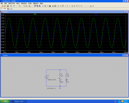
Elvee, you have non-linear capacitor models in Spice? If not, then the distortion simulated is Spice FFT setting error.
How can LTSpice can measure *real* parts ?I was curious enough to make the test myself;
I'm often surprised how often i read "Measured" in forum, instead of "Simulated".
Last edited:
LTSpice imports and exports .wav just fine - can use all of the waveform analysis tools on imported .wav from a external hardware experiment - perhaps Audacity for free playing of test .wav and capture of result
http://web.audacityteam.org/
for analysis I like the greater control you get with free MatLab workalikes - SciLab is the one I've used most so far
Home - Scilab
the cool kids now are ditching purpose designed math/scientific computing sw in favor of Python and the "SicPy" libs SciPy.org — SciPy.org
http://web.audacityteam.org/
for analysis I like the greater control you get with free MatLab workalikes - SciLab is the one I've used most so far
Home - Scilab
the cool kids now are ditching purpose designed math/scientific computing sw in favor of Python and the "SicPy" libs SciPy.org — SciPy.org
Last edited:
You should probably try to explain LTspice that it isn't allowed to make vectorial additions, just arithmetic ones...
You think there's an error in LTspice? Unlikely. Possible, but unlikely.
Jan
.AC, fft both use complex values
in .AC stability and other analysis rely on ratioing complex valued signals
but there are some limitations in when and where complex values are allowed/used/are legal input in LTSpice - why you could want to use more general math sw
in .AC stability and other analysis rely on ratioing complex valued signals
but there are some limitations in when and where complex values are allowed/used/are legal input in LTSpice - why you could want to use more general math sw
You think there's an error in LTspice?
Jan
No.
Attachments
- Status
- Not open for further replies.
- Home
- Member Areas
- The Lounge
- John Curl's Blowtorch preamplifier part II