I am jumping thru this by leaps and bounds... A dual regulated tracking supply has both supplies increase or decrease thier output voltage simultaniously. This results in preservation of balance with respect to ground (common) both statically and dynamically.
Though voltage changes of a regulated supply may be small, high precision circuits are adversly affected by poor balance and common-mode (CM) rejection of the amplifier is also adversely affected by nonsymetrical operation of the + and - power supply.
Thx-RNMarsh
Though voltage changes of a regulated supply may be small, high precision circuits are adversly affected by poor balance and common-mode (CM) rejection of the amplifier is also adversely affected by nonsymetrical operation of the + and - power supply.
Thx-RNMarsh
Quote:
Originally Posted by Kindhornman
Christophe,
I may be wrong here but I think that what Richard is pointing at is a regulated tracking power supply.
Yes I am. At least for low-medium current apps
No one word about regulated trackinng supply...On a SIM of a power supply for a 250W power amplifier, two 10,000 mfd caps were bridged with another 10,000 mfd cap (2X voltage rating, of course) and when an 8 ohm load was switched across one rail or the other, the delta or rail voltage difference was minimal. A physical supply was made with same results.
An app might assume a current feedback power amp without regulated output stage. What would you do to help the amplifier via the PS?
Thx-RNMarsh
So, in that case, the regulation will have to take place outside that component and as close as possible to it.
I think that you guys worry too much. OPPO doesn't use tracking supplies, and neither do I with the Vendetta or Blowtorch power supplies. The servos take up any slack.
Well, for OPAs, and line levels, the current consumption is so little, because the charges are high impedance, that PSU is rarely a problem.
There is a lot of VERY low noise regulators, witch can be used, rejecting any rail noise to the quantum level.
We can even overkill with the use of global serial regulation and shunt regulators on each OPA.
Once at quantum levels, some mysterious devices can help 🙂
There is a lot of VERY low noise regulators, witch can be used, rejecting any rail noise to the quantum level.
We can even overkill with the use of global serial regulation and shunt regulators on each OPA.
Once at quantum levels, some mysterious devices can help 🙂
Last edited:
When you have differential mode swing on the power supply rails you are swinging the ground or challenging the Common Mode Rejection Ratio.
For power amplifier, the cap between + and - rails might work only in case of bridged amplifiers, when load current flows from OUT1 to OUT2 and not to the ground.
Different topologies will have different sensitivities to power supply rail swing. One size as it were does not fit all. For the ones that have been conjured to be as symmetrical as feasible the tracking magnitudes approach makes sense. But I can produce examples of designs whose negative rail sensitivities may be greater than or less than the positive rail sensitivities.
Frankly, it's pretty easy to make amplifiers with low rail sensitivity. And I'd start there, and if desired go on to further "assurances" from stiffer supplies. But a design with high sensitivities is usually a bad sign, often the mark of the tyro who has gotten intoxicated with simulation results.
Frankly, it's pretty easy to make amplifiers with low rail sensitivity. And I'd start there, and if desired go on to further "assurances" from stiffer supplies. But a design with high sensitivities is usually a bad sign, often the mark of the tyro who has gotten intoxicated with simulation results.
Witch don't care, anyway.For power amplifier, the cap between + and - rails might work only in case of bridged amplifiers
Different topologies will have different sensitivities to power supply rail swing. One size as it were does not fit all. For the ones that have been conjured to be as symmetrical as feasible the tracking magnitudes approach makes sense. But I can produce examples of designs whose negative rail sensitivities may be greater than or less than the positive rail sensitivities.
Frankly, it's pretty easy to make amplifiers with low rail sensitivity. And I'd start there, and if desired go on to further "assurances" from stiffer supplies. But a design with high sensitivities is usually a bad sign, often the mark of the tyro who has gotten intoxicated with simulation results.
Yes start with good PSRR it isn't that hard.
Thanks for the Gateways book info. The $10 copy was like new.
That's a deal! I am sure you will enjoy it. He manages to pack in so much good stuff. Interesting story about him that comes up in a search. He left us too soon.Yes start with good PSRR it isn't that hard.
Thanks for the Gateways book info. The $10 copy was like new.
When John Norris, a fine mathematical physicist and (later) astute programmer and theoretical acoustician, asked me for an introductory book on electronics, I gave him a copy as a going-away-from-Harman present 🙂 I paid list 😱
One ought to not complain if a current-mode feedback amp circuit hasnt high (enough) PSRR built into it. IF the PS used today is just good enough.
The only change to existing design is in the reference voltage. One is fixed and the other is referenced to the other rail voltage (thru a divider, typically). Even 3-terminal regs can be modified to run this way.
With JC and others stating so many subtle things make audible differences... how will you know without trying it? Of course, you can assume it isnt important enough. Or, no IC opamp or descrete will benifit. Your call. I know what I do with my amp circuits.
back to Gm and slew rates.... Take it away, john !
Thx-RNMarsh
Still confused, as I see it for load current variation, a large capacitor across +/- (collectors of complimentary emitter followers) will cause the collectors to track (in phase, i.e both increase or decrease simultaneously) . That is the drop on a given collector will not decrease but rather match the opposite collector, and become load symmetrical (ie a full sine instead of a clipped one).
This capacitor will reduce the difference in voltage (due to load variaton) between one collector relative to the other (i.e sum of dc supplies with reducing ripple), where as relative to ground I don’t think there should be any change.
On the other hand making all filter capacitors current more sinusoidal and removing the large return current from the ground (if one were to split the single cap into two) may be more beneficial.
Thanks
-Antonio
I thought to have demonstrated the contrary .where as relative to ground I don’t think there should be any change.
The last choke implementation would be good before a regulation, as it both reduce the absolute level of ripple and noises at HF, where some emitter follower can be too slow and symetrise the ripple at low frequencies, where regulation will kill it with ease.
Regulation will reduce the coil internal added impedance.
Last edited:
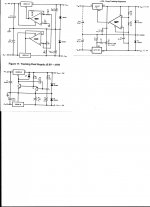
Moving right along --- attached are some Texas Instru apps for 3-term regs for dual tracking regulators.
If you needed just one voltage... they made a 3-term reg for you. If you need bipolar supply, they show you how to use the 3-term reg for those supplies... they are tracking regulated supplies. One could put a pair of Jung/Didden as Tracking Regs as well. Why audio got started on two single 3-term regs or independant supplies, when dual bipolar supplies were needed is beyond me. Fewer parts... cheaper because no additonal opamp or discretes? For High-End maximum performance? ... you decide. C-Multiplier? others? Do the SIM's, do the tests, do the listening. Thx-RNMarsh
If you needed just one voltage... they made a 3-term reg for you. If you need bipolar supply, they show you how to use the 3-term reg for those supplies... they are tracking regulated supplies. One could put a pair of Jung/Didden as Tracking Regs as well. Why audio got started on two single 3-term regs or independant supplies, when dual bipolar supplies were needed is beyond me. Fewer parts... cheaper because no additonal opamp or discretes? For High-End maximum performance? ... you decide. C-Multiplier? others? Do the SIM's, do the tests, do the listening. Thx-RNMarsh
Attachments
Last edited:
If i had to design a high end preamplifier, i would definitely go for a battery (Lithium ion) operation. Ground noise is more a problem than PSU's ones.
A charging circuit, providing more current than the preamp consumption, and a signal sensor circuit witch automaticaly isolate the preamp from AC (including earth) when any signal played.
A charging circuit, providing more current than the preamp consumption, and a signal sensor circuit witch automaticaly isolate the preamp from AC (including earth) when any signal played.
Christophe,
Wouldn't the battery just act as a capacitor in effect if it was attached to a charging circuit? If you are playing music wouldn't the battery be under a constant load and need to be charging to keep the voltage constant and not on a downward slope?
Wouldn't the battery just act as a capacitor in effect if it was attached to a charging circuit? If you are playing music wouldn't the battery be under a constant load and need to be charging to keep the voltage constant and not on a downward slope?
No, the idea is to unplug the preamp from AC when you listen to music, in order to have no ground leakeage currents. Impedance of a battery pack is very low and don't have any HF problem.
Can keep enough voltage for hours.
Can keep enough voltage for hours.
Last edited:
Kindhornman, it is not important to keep the voltage constant on the time scale of a battery discharging under the load of line level circuits.
Okay.
I understand that you could do this at line level, but at the power amplifier side we would be back to a similar situation that we have just eliminated in the line level side. What would the overall elimination of ripple on the line level side do for the power amplifier side. Is this a multiplicative reduction or only an additive reduction in distortion ultimately?
I understand that you could do this at line level, but at the power amplifier side we would be back to a similar situation that we have just eliminated in the line level side. What would the overall elimination of ripple on the line level side do for the power amplifier side. Is this a multiplicative reduction or only an additive reduction in distortion ultimately?
- Status
- Not open for further replies.
- Home
- Member Areas
- The Lounge
- John Curl's Blowtorch preamplifier part II