I might open another item and ask for real results again. The power supplies, regulated power supplies. I would be very interested to see both low frequency and HF FFT spectra measured at the rails of different regulated power supply designs. This would prove or demystify claims about efficiency of different designs regarding both noise in audio band and suppression of high and very high frequencies.
I agree also with the inductance vs freq....goes to path of least resistance... towards the surface of the conductor where the L is lowest.
Do not agree on your explaination regarding the fields. Perhaps just a different view of the same thing? -RNM
http://www.phys.uri.edu/~gerhard/PHY204/tsl243.pdf
jn
ps..Becker had the same text, I was actually looking for a drawing online which shows it. For now, the calculations from some code I wrote. Top is the wire, bottom is B. Note it rises linearly from wire center to wire surface, then as 1/R out of the conductor.
pps. Found some with supporting pictures, all ya hafta do is google "magnetic field inside wire", the nj ppt link is an AP physics course for high school. Page 8 has the equations, 9 has the drawing. I won't copy the drawing and paste it here, but it basically duplicates the drawing I posted.
Attachments
Last edited:
I think I see part of what you are talking about but still don't recognize most of what you are asserting - rather than citing sources - what's so hard about pointing us to the names, equations?
Hall effect is considered the beginning of quantum effects - not classical EM, which describes purely linear conductors, infinitesimally divisible charges, currents - ultimately put together, described by Maxwell's equations
at any point where DF6, I or others talked about Classical EM, Maxwell's equations, linear conductors you could have said whether the effect you are describing is a quantum effect
I suppose we could argue over whether “ordinary magnetoresistance” is purely classical
Magnetoresistance - Wikipedia, the free encyclopedia
if we're getting close to whatever effect you still haven't referenced - we can look at the equations, put some numbers on carrier mobility in metals, resistive films, under the influence of magnetic fields that may be encountered in home audio on boards already designed to avoid inductive coupling to nonlinear PS rail, Class AB stage currents
for a start the field at the center of a 1 cm loop carrying 1 Adc is ~ 6 uT,
single digit Amps of current in reasonably sized Cu wires gives average electron velocity <mm/s
the (way) sub ppm level effects of “ordinary magnetoresistance” for ordinary circuit design seems easy to miss in the much larger % level effects of linear partial mutual inductance proximity effect
What is the level where it is no more important ?Please give it a break, PMA. 7th harmonic is STILL very important.
I think I see part of what you are talking about but still don't recognize most of what you are asserting - rather than citing sources - what's so hard about pointing us to the names, equations?
Skin...
File:Skineffect reason.svg - Wikipedia, the free encyclopedia
note the explanation...
The current redistributes because the eddies are opposite in the center, they cancel there but reinforce on the surface.
Now, consider an external source and a cylindrical sheet of current such as a metal film resistor. the eddy currents will cause a redistribution on the cylindrical sheet. Since the current on the sheet is what is causeing the external magnetic field, the current tries to redistribute as close to the external wire as it can because it's the path of least reactance.
With a copper conductor, the variation in resistance is not very large. With a cylindrical sheet of resistive material, it is not.
It's not a quantum effect..
jn
Thanks very much to PMA for the excellent comparative measurements and for the striking conclusion, that despite these tiny numbers an ordering of sound qualities is still possible.
One possible explanation is that the devices' intrinic (pre-feedback) linearity is important, but not ordinarily measured. Another is that the devices' monotonicity, or lack thereof, of linearity with signal level is important, but not ordinarily measured. Crossover distortion is one example of a well understood imperfection that is poorly tested for conventionally.
Thanks again,
Chris
Thanks Chris, for bringing that up. I usually estimate what something will sound like by its open loop transfer function as well, but I did not want to incur further criticism by bringing that up here.
For the record, the IC op amp that I use in place of the AD797 has to amplify over 30 dB or 40 times and has a final load of 800 ohms above 2KHz. Not so easy as some might guess.
please, john, the "poor me" and the arrogance really don't mix well
feedback only works well for a fairly linear open loop - can't magically bridge a deadband only try to push faster trough it - with limited success
but the when the amp is free of deadband, abrupt gain changes then feedback over a certain level does reduce all orders of "locally Lipschitz" nonlinearities where the feedback factor is large
and much of the pious "make the amp as linear as possible before applying feedback" is in reality just choosing how to distribute feedback between local, and larger loops up to the global feedback
once you have decided how many, what type and how heavily biased the gain elements are
op amp open loop linearity plots are rare, but appeared at least 3 decades ago in some (PMI) datasheets - Pease has written on this - published test circuits, plots - it really is text book (or app note) engineering today
if monolith op amp designers don't show you then measure it, if they choose too low bias current, too small output Q, then bias, buffer the output if you like the rest of the specs - if not pass it by
you could even look at less than 20 yr old op amps
Last edited:
-200dB and no mains noise
Here's an interesting physics paper. Notice the noise graphs, no mains lines at all. http://physics.syr.edu/~bplourde/papers/RSI-Heitmann08-voltmeter.pdf
Here's an interesting physics paper. Notice the noise graphs, no mains lines at all. http://physics.syr.edu/~bplourde/papers/RSI-Heitmann08-voltmeter.pdf
It should and must only be LME 49990 Ic.For the record, the IC op amp that I use in place of the AD797 has to amplify over 30 dB or 40 times and has a final load of 800 ohms above 2KHz. Not so easy as some might guess.
...apparently incorrect claim that it is what distinguishes ICs from discrete, relegating the former to "mid fi."
No one doubts that AD797 and OPA637 are excellent (and comparably expensive) parts but you won´t
find them in "mid fi" where the design decisions are made by bean counters.
Would be interesting to see the results for JRC4580 and similar dual opamps you
typically find in consumer gear. (But maybe PMA does not store such junk in his lab. ;-) )
and much of the pious "make the amp as linear as possible before applying feedback" is in reality just choosing how to distribute feedback between local, and larger loops up to the global feedback
Another *possible* description (not testable AFAIK, so not even a hypothesis) is that intrinsic linearity, before even local feedback, is important. Sounds wacky at first blush, but does go a long way towards explaining such strange things as the ease with which good sound is obtained with vacuum valves, the SET phenomenon, folks' preference for FETs, etc. Maybe it's all self-delusion, but maybe there's some there there.
Thanks,
Chris
Yes, Chris and jcx say sooth.
In a given small-enough region of operation, our assumptions are that a series expansion of some number of terms accurately describes the nature of the beast, and when feedback is applied it reduces distortion in a predictable way. Thus we are allowed to do the measurements with high noise gain and extrapolate to much lower gains. And the curve of growth of higher-order terms is likewise predictable as a function of level.
In a given small-enough region of operation, our assumptions are that a series expansion of some number of terms accurately describes the nature of the beast, and when feedback is applied it reduces distortion in a predictable way. Thus we are allowed to do the measurements with high noise gain and extrapolate to much lower gains. And the curve of growth of higher-order terms is likewise predictable as a function of level.
I'm sure you've seen the theoretical paper of Boyk and Sussman that's floating around, afaik never published in a journal although looking journal-ready to these eyes at least. Sussman is a technical heavy hitter, apparent from his publications and attested to by Scott W.Another *possible* description (not testable AFAIK, so not even a hypothesis) is that intrinsic linearity, before even local feedback, is important. Sounds wacky at first blush, but does go a long way towards explaining such strange things as the ease with which good sound is obtained with vacuum valves, the SET phenomenon, folks' preference for FETs, etc. Maybe it's all self-delusion, but maybe there's some there there.
Thanks,
Chris
They deal with ideal models, with appropriate qualification, of FETs, bipolars, and tubes, and look at IM distortion terms arising from very simple structures with local feedback. Someone will have the ref link I'm sure, or I can dig it up.
But in essence, it's a kind of elaboration of the old Baxandall stuff about higher order terms of HD appearing with small amounts of feedback around nonlinear systems, even though the overall performance by some measures is enhanced.
I suspect the focus on IMD, versus HD, makes it a little more relevant to what we seek.
Would be interesting to see the results for JRC4580 and similar dual opamps you
typically find in consumer gear. (But maybe PMA does not store such junk in his lab. ;-) )
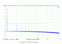
No I do not 😉. But the last page of my zip/pdf that was posted here several hours ago shows uA748. Or precisely MAA748, the Tesla equivalent of uA748, with Ccomp 10pF, which makes it faster than uA741 (equals Ccomp 30pF). If you want to laugh, here it goes again: (noisy and with THD increasing fast with frequency)
Attachments
- Status
- Not open for further replies.
- Home
- Member Areas
- The Lounge
- John Curl's Blowtorch preamplifier part II