When i go balanced i prefer the INA topology. See my FPS MC Phonostgae in Jan Diddens Linear 0 compilation. It is balanced from input to output, even the RIAA is fully balanced. Comes with a 3dB noise panalty with the same amount of input devices. It has around 0.5nV/qHz and my best parlle symmetric efford goes down to 0.3nV/qHz and then using even more input transistors in parllel does not really help any more exept you want more gain in the input stage.
For Super Low Noise MC duty is use Lundahl transformers. If that is realy balanced is another question.
For Super Low Noise MC duty is use Lundahl transformers. If that is realy balanced is another question.
What the world needs is a transfomer
bassed solution to making the Sony
tuner loose it's ' grain ' 🙂
😀
se
For your interest, I just published some measured characteristics of different complementary JFETs at Nelson's
As you can see, the beloved K170 / J74 are not quite complementary as we wish to think.
You will find that the optional pot used for tweaking the
Source resistance of the Jfets will give you a nearly perfect
3rd harmonic distortion for the amplifier, which indicates
that the compound performance of all four devices is well
matched.
😎
For Super Low Noise MC duty is use Lundahl transformers.
Now yer talkin'!
'Cept I prefer CineMags. 😀
If that is realy balanced is another question.
Depends on the particular transformer.
The Jensen's and CineMag's have a symmetrical primary so the input is balanced. However because of how the secondaries are wound, they have a bit of imbalanced due to capacitance.
Of course you could use a pair of them to get a balanced output as well, and if you wire the primaries in parallel, an additional 6dB of gain.
se
As far as i learned it the input would only be REAL balanced when the cartridge would have a center tab so 2 x 3 wires go to the input of the transformer for stero. I know, this discussion what is balanced and what not existed since day one and will go on forever so forgive me if my opinion is on the wrong side of your event horizon.
A good shielded output transformer might be perfect for the output here. Kind of expensive, it might fit.
> Sometimes even a 1kOhm gate stopper does not do the trick.
Guten Morgen Joachim,
How about a cap to parallel the drain resistors of the 1st stage, or a cap between the rail and the gate of the second stage (after the gate stopper) ?
Patrick
Guten Morgen Joachim,
How about a cap to parallel the drain resistors of the 1st stage, or a cap between the rail and the gate of the second stage (after the gate stopper) ?
Patrick
As far as i learned it the input would only be REAL balanced when the cartridge would have a center tab so 2 x 3 wires go to the input of the transformer for stero.
If the transformer's primary winding is symmetrical and the cartridge's coils are symmetrical, then they would be balanced. No need for a center tap.
se
A good shielded output transformer might be perfect for the output here. Kind of expensive, it might fit.
Why would it need to be shielded for an audio output?
If you absolutely need it shielded, CineMag's ultra-balanced, ultra-isolation CMOL-2x600T2 would fit the bill, but at over $150 it is kind of expensive.
If you don't need shielding, their CMOB-4 I think is around $35.
se
EUVL., i usually use an RC combination for examle 100 Ohm and 22pF to limit the response at the input. This parts have to be high quality especially the cap and i like silver mica best in that position. You could also try a coil of 1.2uH in series, maybe with a 60 Ohm resistor in parallel. In fast buffers sometime the problem comes from the output impedance so you get a response up to 30MHz for example, then you get a notch and then the response recovers again because of some strange forward coupling effect. This has to do with the unlinear output and input capacitance of Fet and Bipolar transistors so i usually prefer transistors with a low Cob. See some simulations here in the attatchement. To help you any further i whould need your exact schematic and there is no way around to actually build it because on a PCB a lot of stray effect happen.
atb, joachim
atb, joachim
Attachments
Very kind of you Joachim.
I shall try to put together a schematics this weekend.
And I know I have to build it eventually to be sure.
Just too many ideas and too little resources, especially time.
Herzlichen Dank,
Patrick
I shall try to put together a schematics this weekend.
And I know I have to build it eventually to be sure.
Just too many ideas and too little resources, especially time.
Herzlichen Dank,
Patrick
I think that johnloudb's approach is the best path (IN THIS CASE) for a number of reasons: First, cost. We are modifying a $75 tuner for goodness sake. Transformers, good ones, cost real money and can be physically rather large. Of course, they could be mounted OUTSIDE the case. Then hum pickup is almost inevitable, without serious shielding. Inside, what would the RFI internal environment do to an unshielded transformer.
Second, we only have 8.5V and 7ma or so for both channels. Most IC's would starve the output stage to speed up and quiet the input stages.
Third, the jfet follower, properly done is almost perfect for a hi Z load of 10Kohms or so. 600 ohms, NO WAY, but 10Kohms, OK.
I not only use this topology for impedance conversion in the Parasound JC-1 power amp, but we first used it before the Blowtorch preamp was made into a product. The biggest problem was lack of voltage gain, not sound quality.
We don't really need the extra gain in a buffer stage for this Sony.
That should be enough reasons.
>Then hum pickup is almost inevitable, without serious shielding
Remember this is 'line' level
Remember this is 'line' level
Joachim,
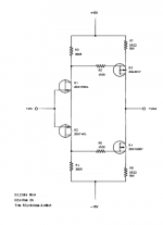
Schematics as promised.
Thx,
Patrick
PS
The graphic conversion blurred things.
The input JFETs are K170/J74, Idss 8mA. Drain resistors 360R.
The drivers are K1530/J201; source resistors 0R22, gate currently at 470R.
I should have added a load at the output perhaps, of say 100R or less.
Speaker impedance goes in parallel, without saying.
.
Attachments
Last edited:
So the signal goes out of the drain of the output transistors ? I whould add a trimmer between the sources of the input Fets of ca.50 Ohm. The middle pin whoud go to earth and you can conveniently adjust offset.
So the signal goes out of the drain of the output transistors ? I whould add a trimmer between the sources of the input Fets of ca.50 Ohm. The middle pin whoud go to earth and you can conveniently adjust offset.
Offset will probably change with temperature. Servo is better.
Oh, actually one huge mistake -- output should also go to the JFET source.
🙁
Patrick
🙁
Patrick
Attachments

Last edited:
- Status
- Not open for further replies.
- Home
- Member Areas
- The Lounge
- John Curl's Blowtorch preamplifier part II