You keep asking us to do messy algebra, but have not told us why. Therefore it seems premature to conclude that we don't understand. Tell us what it is that you believe you understand, and we (allegedly) do not. We have already established that there will be an infinite series. The significance of the higher order terms depends entirely on the signal level, which you have not told us.
You seem to be the only one even trying. The issue is simple if I have two amplifiers with different distortion mechanisms is the final distorted product the same if I connect then in series with global feedback or in series with each having local feedback, both configurations are set to the same gain.
So if A1o = 1000 x (A1i + .01 A1i exp 2 + .01 A1i exp 3) and A2o = 1000x (a2i + .05 A2i exp 2)
A1 set to Av=10 would approximate A1o = 10 x (A1i + .0121 x A1i H2 + .0121 x A1i H3 + .0000221 x A1i H4 + .000221 x A1i H6 + .00000008 x A1i H8 +.00000133 x A1i H9 + .00000001 x A1i H12)
A2 set to Av=10 same way would be A2o = 10 x (A2i + .0805 x A2i H2 + .018973 x A2i H4 + .00000098 x A2i H16)
So in series A1 first the output would be Ao = 10 x (Ai + .02015 x Ai H2 + .0121 x Ai H3 + .00211 x Ai H4 + .000221 x Ai H6 + ..0000191x Ai H8 + .0000133 x A1i H9 + .00000001 x Ai H12 + .00000001 x Ai H16 + .0000001 x Ai H18)
With A2 first Ao = 10 x (Ai + ..8174x Ai H2 + .0121 x Ai H3 + ..01899 x Ai H4 + .0000221 x Ai H6 + ...000189Ai H8 + .00000133 x A1i H9 + .00000001 x Ai H12 + .0000001 x Ai H16 + .00000001 x Ai H18)
If both were placed in series with global feedback Ao = 10 x (Ai + .0726 x Ai H2 + .0121 x Ai H3 + .0007956 x Ai H4 + .0001326 x Ai H6 + .0000007956 x Ai H8 +.0000133 x Ai H9 + .00000036x Ai H12)
I probably made some mistakes in the truncations and typing but I think the difference is quite clear. (Actually I am pretty sure I screwed it up so this is subject to revision for absolute values but the point probably won't change.)
When you use local feedback, the earlier the stage the more important the distortion contribution. Lower distortion stages should provide more gain.
When global feedback is used the overall distortion can be lower but the higher order products will be greater.
Last edited:
No PMA, this is new, let's talk about it.
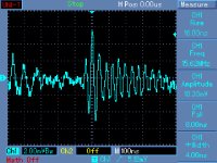
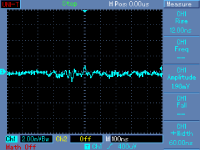
These plots depend only on topology of 2 different preamplifiers. They are measured at analog output, pot at minimum.
15.62MHz is a LED/LCD display driver frequency. All that mess comes through PSU and PSU rails. This is a nowadays reality.
Attachments
Last edited:
If I weren't a complementary-symmetry kind of guy, it would be interesting to play around with the EPC devices. These are lateral parts with extremely high transconductance -- the best of both worlds. Too bad they can't use their process to make a P-channel part...
I have some on order, hopefully there when I get back. Who knows what
they might do.
Of course we can get our symmetry from a circlotron...
😎
I'm not sure what that says about me, but I'm sure someone will helpfully tell me!simon7000 said:You seem to be the only one even trying.
I think you need to check the algebra. Your total gain is 10, and should be 100. A2 with feedback has no ^3 term, yet I would expect it to be larger than the ^4 term.
Making comparisons like this needs to be done carefully, as the formulas are cast in terms of input voltages, yet we normally want to compare at the same output voltage. Given two amps, then they should be cascaded with the one with higher distortion coefficients first as this will have smaller signal levels. Feedback doesn't change this.
Two lots of 'local' feedback vs. global feedback? For the same output voltage, the best option is to put the most distorting one first and use global feedback. This puts the smallest signal through the most distorting amp, so total distortion is less. Global feedback means the first stage has a much smaller output, so again reduces distortion. Of course, all this assumes that the amp transfer functions are low order polynomials, and that everything has a flat frequency response. Real life is more complicated.
I'm not sure what that says about me, but I'm sure someone will helpfully tell me!
I think you need to check the algebra. Your total gain is 10, and should be 100. A2 with feedback has no ^3 term, yet I would expect it to be larger than the ^4 term.
Making comparisons like this needs to be done carefully, as the formulas are cast in terms of input voltages, yet we normally want to compare at the same output voltage. Given two amps, then they should be cascaded with the one with higher distortion coefficients first as this will have smaller signal levels. Feedback doesn't change this.
Two lots of 'local' feedback vs. global feedback? For the same output voltage, the best option is to put the most distorting one first and use global feedback. This puts the smallest signal through the most distorting amp, so total distortion is less. Global feedback means the first stage has a much smaller output, so again reduces distortion. Of course, all this assumes that the amp transfer functions are low order polynomials, and that everything has a flat frequency response. Real life is more complicated.
I know I got the arithmetic wrong and you got it right about what I got wrong. My model only had 10x for the signal from the stacked pair but distortion products 100x. But as it is the fuzzy thinking part of the day, I'll get to it later.
The actual issue is that if you know the distortion per stage it is possible (but not so easy) to adjust the gain in each stage to tailor the overall distortion. Minimum distortion is probably not the goal as higher order products most consider to be worse.
There is an inherent assumption in your distortion stage logic and that is distortion decreases with signal level. That is not always the case.
As to what trying says about you is only good!
These plots depend only on topology of 2 different preamplifiers. They are measured at analog output, pot at minimum.
15.62MHz is a LED/LCD display driver frequency. All that mess comes through PSU and PSU rails. This is a nowadays reality.
Very true reality! I have just been EMC-qualifying some industrial displays, and can vouch for the difficulty in removing emissions at the frequency of the Dot-Clock [pixel rate] of the HD flat panels. For 1366 x 768, look out for 65-75MHz, radiated, and for 1920 x 1080, ~ 150MHz is very stubborn. The LVDS interface emits badly if there is any asymmetry in the physical interconnect, and the LCD drivers add to the problems.
The CCFL backlights in some of the panels have huge emissions around 100kHz, too - this is too low a frequency for the statutory testing, but not too low to spoil your amplifiers.
Try turning OFF that cheap flat-panel TV while listening, and check for the difference!
Finite polynomial transfer function almost guarantees this. It definitely guarantees it for sufficiently small signals. Discontinuous functions create trouble, but we know they will sound horrible anyway. Crossover distortion should not be discontinuous but might require an infinite polynomial, and is usually in the last stage only.simon7000 said:distortion decreases with signal level
Of course we can get our symmetry from a circlotron...
You took the words right out of my mouth!
Floating power supplies...
Not a great idea with high-impedance tubes driving the non-linear capacitance to the AC power grid, but certainly a possibility for solid-state circuits. Then the interesting question becomes the driver stage and phase splitter.
If I didn't have a dozen other products on my plate, I'd race you.
As it is, if we come out with one later, please don't say we copied you!
These plots depend only on topology of 2 different preamplifiers. They are measured at analog output, pot at minimum.
15.62MHz is a LED/LCD display driver frequency. All that mess comes through PSU and PSU rails. This is a nowadays reality.
Yes, this is indeed ugly stuff. You want to know what it does to an AP system in a lab where theres about 20 TV's running . . . very tough to get clean plots unless you can get into a shielded room. CFL and the new LED lamps also radiote a lot of bad stuff.
Having said that, some ferrites on the input and output of the PSU for conducted noise would probably sort this out, though I know some people believe they affect the sound. Of course, radiated noise is a different matter.
PMA, do you care to share the detials and test set-up with us that gave you these scope plots?
PMA, do you care to share the detials and test set-up with us that gave you these scope plots?
Last edited:
Jan, can you point out to me where Bruno mentioned PIM in his article?
John, you are right, he didn't mention PIM.
jan didden
Listener perception is everything where I come from. No distortion
analyzer has ever purchased one of my amplifiers.
I recall Bruno's article as being a nice overview of his thinking - obviously
I must have missed a proof as profound as you describe. As I have the
disadvantage of being at the coast, you will have to wait until I get back
for my response, unless you would care to email me another copy of the
piece.
😎
Hi Nelson,
I will email you an e-version.
Yes of course, listener preference is all that matters for selling an amp. That is of course not disputed.
Bruno is dispelling several mytes: of 'slow' and 'fast' amplifiers for instances, he shows ' a slow amp with lots of feedback' and a 'fast amp with little feedback' ; says nothing about the linearity of an amp at audio frequencies, that loop gain at audio frequencies is all that matters to make it linear, and that if that loop gain rises to very high values at low freq may * look* like it is a low bandwidth amp, but that the only thing matters is loop gain at the upper audio range.
And a few other things. Anyway, don't expect me to repeat his findings here. The important thing I would think is that he painstakingly takes the trouble to explain, to argue, to document many important issues in audio engineering. It's very possible that he errs somewhere, and I will be the first to run a Letter that points that out.
But I get so very tired of people saying: "he's wrong, and I asked my friend, and my friend says I'm right". Surely anybody worth something in audio would be able to come up with a somewhat more intelligent comment. Or shut up, if only in respect to those who DO try to do their homework.
jan didden
[snip]When you use local feedback, the earlier the stage the more important the distortion contribution. Lower distortion stages should provide more gain.
When global feedback is used the overall distortion can be lower but the higher order products will be greater.
Interesting Ed. I must say the result is somewhat intuitive for me, but I never worked it out this way. Is your first statement not analogous to the situation concerning noise contribution, where the first stage noise contribution has the greatest impact on the total noise contribution?
Looking forward to your article 😉
jan didden
Right on, Nelson. His 'history' could use a little correction as well. IF he had asked, one of us, either Walt or me, could have brought him back to the right track. There is nothing new here. PIM is what I look for, not TIM, we solved the TIM problem over 35 years ago.
Well of course nothing stops you or Walt or whoever from sending me a mail with the 'corrections'. Should I reserve space in the next issue for you?
jan didden
Or shut up, if only in respect
Or give the dark side a try, before posing off as an oracle, or something along those lines.
(i disagree with any one, much easier)
Didn't he mention SID Vicious ?
http://www.youtube.com/watch?v=WIXg9KUiy00
Last edited:
Or give the dark side a try, before posing off as an oracle, or something along those lines.
[snip]
Jacco, I give any side a try, I'm an equal side publisher 😉
But there must be some substance to try.
jan didden
Finite polynomial transfer function almost guarantees this. It definitely guarantees it for sufficiently small signals. Discontinuous functions create trouble, but we know they will sound horrible anyway. Crossover distortion should not be discontinuous but might require an infinite polynomial, and is usually in the last stage only.
Testing components for discontinuities is currently on my bench, but I am still tied up in more urgent projects (2 churches, 1 Arena, 1 football stadium design.)
Interesting Ed. I must say the result is somewhat intuitive for me, but I never worked it out this way. Is your first statement not analogous to the situation concerning noise contribution, where the first stage noise contribution has the greatest impact on the total noise contribution?
Looking forward to your article 😉
jan didden
Actually for the article I will show no math! Since no one other than DF96 seems to understand it there will only be plots of actual devices. I promised a short article. Four plots and a few hundred words should do it.
I understand it, I'm just too lazy and unmotivated to set up a numerical solution. 😀 In an article, you should absolutely go through the math- "What's more difficult for the author is easier for the reader."
If memory serves, there was a derivation of this in Elmore and Sands?
If memory serves, there was a derivation of this in Elmore and Sands?
- Status
- Not open for further replies.
- Home
- Member Areas
- The Lounge
- John Curl's Blowtorch preamplifier part II