$400-$440 for the transformers we chose.
And that toward a $17000 preamp?
Personally, I find that the playback environment that I normally use in my home listening conditions does NOT need the galvanic isolation of an input transformer, and I generally do not use it.
The benefit of galvanic isolation doesn't really have to do with the playback "environment." You're thinking of common-mode rejection, which is something completely different.
Galvanic isolation addresses issues having to do with interchassis leakage currents.
se
$400-$440 for the transformers we chose.
For the LL1931 and 1933?
se
One of the real advantages of a V-I input stage is that you can add a parallel RC combination on the output to create the high frequency rolloff of 75 uS that is necessary for part of the RIAA, and at the same time, INTEGRATE the input signal, so that the very fast ticks and pops, as well a cartridge mistracking, are smoothed out, and partially removed, increasing headroom. This design approach has been used by me in the JC-80, Vendetta Research SCP-2, and the new Constellation Orion preamp under construction.
The newly released Parasound JC-3, being IC in construction, uses a slightly different EQ configuration. (more later)
The newly released Parasound JC-3, being IC in construction, uses a slightly different EQ configuration. (more later)
One of the real advantages of a V-I input stage is that you can add a parallel RC combination on the output to create the high frequency rolloff of 75 uS that is necessary for part of the RIAA, and at the same time, INTEGRATE the input signal, so that the very fast ticks and pops, as well a cartridge mistracking, are smoothed out, and partially removed, increasing headroom. This design approach has been used by me in the JC-80, Vendetta Research SCP-2, and the new Constellation Orion preamp under construction.
The newly released Parasound JC-3, being IC in construction, uses a slightly different EQ configuration. (more later)
I'm astonished at this posting but I suppose I shouldn't be. Cartridge mistracking resulting from geometric misalignment between the playback stylus and cutting stylus due to incorrect installation, pivoted tone arms and also due to the goove modulation exceeding the capabilities of the arm/cartridge/stylus characteristics results in non linear distortion which cannot be corrected for later. Only linear distortion can be compensated for by skillful application of filtering (inverse equalization.) The suppression of leading edge transients characteristics of the pops and clicks of vinyl phonograph records is the result of FR characteristics limiting rise time. FR and transient response are two ways of looking at the same thing. It is a typical assignment in an undergradutate electrical engineering course to generate one given the other in either direction. This is the same mistake you posted many years ago on another board, one you not only reversed yourself on but took credit for while assigning the mistake to me. Do I really have to post a link to that? It's still there in that site's archives.
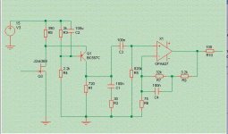
Here is a simple example by Werner that was publshed on DIY Audio before.
2SK369 🙂
One 2SK369 or two paralleled 2SK170 (matched) wont change much. From datasheet, i'd say two K170 are even better (less input capacitance, a bit more transconductance).2SK369 🙂
For DIY, I wouldn't bother to buy K369 when having plenty of K170.
Of course, for commercial adventures/serial production some here are in, using only one part instead of two paralleled, will be the way to go.
Tino
It makes more sense if you read what John actually wrote and attempt to understand it. Maybe you missed the word "headroom"?I'm astonished at this posting... [snip lengthy misunderstanding]
For the LL1931 and 1933?
se
That's full-boat retail at K&K.
And the dollar sucks.
Tino,
regarding capacitance, Crss counts.
Regards,
Agreed!
K170 has typ. 6pF, K369 has 15pF Crss, so I think paralleling is about the same if not slightly better.
I still have the impression that K369 is a somehow doubled K170.
Tino,
you mean, not a halved K147 ?
(makes me wonder when the hearty DIY orientated start to shave off K369's to add some dissipation surface)
you mean, not a halved K147 ?
(makes me wonder when the hearty DIY orientated start to shave off K369's to add some dissipation surface)
It makes more sense if you read what John actually wrote and attempt to understand it. Maybe you missed the word "headroom"?
What I did not miss is the phrase; " so that the very fast ticks and pops, as well a cartridge mistracking, are smoothed out, and partially removed"
That non linear distortion cannot be removed once it is part of the signal would be an elementary fact NO electrical engineer whose specialty is analog electronic circuits would forget, it would be too ingrained, its principle too fundimental to the nature of analog signals. But even those not trained as electrical engineers could learn this fact too, especially if they dealt with it long enough. Now perhaps some clever software engineer who specializes in convolved mathematical processes could one day figure out some tricky way to mitigate this problem through the most ingenius algorithms applied to digital signal processing but short of that it can't be done. There's mathematics to prove that fact. What can be done is to introduce other distortions such as slew rate limiting or FR filtering which reduces output in the part of the passband where you expect distortion products to show up but that technique will only distort otherwise undistorted signals at the same time. An electronics engineer would know that too. A tinkerer on the other hand who designs by the seat of the pants on a hit or miss basis and keeps what he likes might not.
I've never been a fan of sycophants either BTW.
This is a valid statement.What I did not miss is the phrase; " so that the very fast ticks and pops, as well a cartridge mistracking, are smoothed out, and partially removed"
Opamp single stage feedback type phono preamps momentarily go into open loop condition when fed very fast transients caused by the likes of dust grains and mistracking.
This causes dust crackles and mistracking to 'explode' out of the speakers, whilst the two stage phono preamp renders dust grains and mistracking to be relatively benign.
Eric.
As I understand it all that is being claimed is that the 75us corner, present in all RIAA preamps, is best placed sufficiently early that HF-rich signals before it do not create headroom problems. Most preamps do this anyway, as the 75us is either immediately after the first stage or part of a feedback loop around the whole thing.
I can't see anything special about doing this via a transconductance amplifier feeding a CR circuit. It is merely another way of providing sufficient headroom.
It could be misleading to describe this as integration, because true integration continues down to zero frequency. It is just a first order low pass filter, not an integrator.
An op-amp goes 'open loop' if you try to exceed its slew rate limit, and may distort if you approach this limit. So what? Good design will be aware of this. Signal levels are low, so quite 'fast' signals have small slew rates.
Last edited:
Et le Dollar Suce. (censored)
Look deep into my shiny US eyes and repeat after me : Au Contraire.
Attachments
- Status
- Not open for further replies.
- Home
- Member Areas
- The Lounge
- John Curl's Blowtorch preamplifier part II