Assuming the performance goal is zero distortion? What if the goal is listening pleasure?
Since I don't contemplate a career in the fashion audio industry, I use math and instruments when designing. So I have no idea, only a "designer by the ear" could tell.
Since I don't contemplate a career in the fashion audio industry, I use math and instruments when designing. So I have no idea, only a "designer by the ear" could tell.
Sure. However, back in the 50's engineers still had to design stuff without all the great technical tools we have today. And I wouldn't want to go back.
In terms of human factors engineering, in many ways as though we are back in the 50's. Maybe we know the most about that in reference to designing systems to interact with aircraft pilots, especially fighter pilots. But for designing audio amplifiers that are a pleasure to listen to, we know much less. However, as a performance goal, I don't think there is anything wrong or immoral about trying to design amplifiers for something other than minimal distortion.
At a practical matter, for tasks like mixing and mastering, I would very much like to have your best low distortion amplifier. For listening in my car, or for watching movies at home, I think I would probably prefer enjoyment over accuracy. Maybe others would differ on this, I don't know.
Derfy,
Voltage regulation, noise, frequency response, symmetric response, current path and circuit noise damping are all known variables of some importance.
A current shunt need not be a true voltage regulator but we do class it that way.
Too many labels and you sleep in the map.
Voltage regulation, noise, frequency response, symmetric response, current path and circuit noise damping are all known variables of some importance.
A current shunt need not be a true voltage regulator but we do class it that way.
Too many labels and you sleep in the map.
In the case of JC and his products, it might not be unreasonable to suppose that some of his customers have better hearing than he does.
Possible yes. Plausible? At least for the legendary products the owners are possibly a similar age, as neither Vendettas nor Bloworches are sold very often, despite commanding prices higher than new. The target market for high end audio does seem to be grey these days. So raw hearing acuity may not be high.
However they WILL be critical listeners and will actually focus on the music rather than having it playing in the background whilst on the internet like most of us these days.
Well, at least we are talking again about audio quality.
Of course, the usual criticisms are back as well, but for me, I want to design the best that I can afford to get away with. I don't want to make another 'mid-fi' product if I can help it, I want something somewhat better than most competing products. This is why relatively small improvements like high speed, soft recovery diodes can be useful.
And it is a measurable change, if one really wants to test for it.
It is interesting that this problem came in, only with the introduction of solid state power diodes, over vacuum tube equivalents, like the 5AR4 or even the 5U4. Serious designers found that solid state rectifiers were problematic, including me, for tube equipment, and later we found that solid state equipment had a problem with standard power diodes, like the 1N4003, etc. At first, it was not obvious what was wrong, but a consensus of listening experiences, coupled with 'current probe' measurements confirmed that there really was a difference in diode performance, EVEN at 60Hz. Of course, if you have a standard diode bridge with properly designed snubbers, you are mostly there, and going through the hassle of swapping out the diodes might not be advisable. However, with OEM design, why not do it right in the first place, and I do that where I can afford to do it.
For the record, the soldering of my Vendetta Research designs was done by first rate technicians, some lab experienced, one NASA trained, and yet another Swiss trained. We always used SN-62 eutectic solder, and carefully cleaned away any resin or solder droplets. However, some of my designs have been modified by Japanese amateurs, and I suspect that they are not as fully qualified as my technicians at soldering. This is probably where the photos of the Vendetta boards were shown to be compromised. For me, quality soldering and cleanliness are paramount in designs made under my control.
John, why not replace the Vendetta's entire PSU, enclosure and all, with something newer and better?
In the time between the last manufactured Vendetta unit, and today, plenty of improvements have come available. For example, R-core transformers with much MUCH less capacitive coupling from primary to secondary. Much better common-mode chokes. Aluminum polymer electrolytic capacitors with much higher capacitance per cubic mm and much lower equivalent series resistance. Strip-geometry vertical MOSFETs with gigantically increased (W/L) thus gigantically increased transconductance. Opamps with >200 MHz gain bandwidth product. Zetex BJTs with base resistance below 1.6 ohms. 7.5 digit multimeters are now available, allowing you to match resistors much better than ever before, and also to trim |VOUT+| and |VOUT-| within microvolts. Why not come out with the Vigilante Vendatta PSU that really kicks butt?
In the time between the last manufactured Vendetta unit, and today, plenty of improvements have come available. For example, R-core transformers with much MUCH less capacitive coupling from primary to secondary. Much better common-mode chokes. Aluminum polymer electrolytic capacitors with much higher capacitance per cubic mm and much lower equivalent series resistance. Strip-geometry vertical MOSFETs with gigantically increased (W/L) thus gigantically increased transconductance. Opamps with >200 MHz gain bandwidth product. Zetex BJTs with base resistance below 1.6 ohms. 7.5 digit multimeters are now available, allowing you to match resistors much better than ever before, and also to trim |VOUT+| and |VOUT-| within microvolts. Why not come out with the Vigilante Vendatta PSU that really kicks butt?
Thanks Mark, but I already have a new power supply. Vendetta Research power supplies have not been made the same way or in the same box for the last 25 years. However, I have to make updates within the parameters of the box and its circuit board.
However, back in the 50's engineers still had to design stuff without all the great technical tools we have today. And I wouldn't want to go back.
In all truth, on a daily basis, I couldn't care less. Sorry for stating the obvious but, like the steam engine, that period now belongs to the history books. If I need entertainment, I know where to get one.
Hi John,
Rectifier noise can be reduced at the source without going to exotic creations, using our highly engineered, plain jane diodes. Back in tube days, we had to contend with mercury rectifiers (83 for example) that also emitted RF bursts. They still used them and figured out ways to mitigate the problems. I only mention this because there are ways to deal with rectifier spikes and short conduction angles. (Hint:conduction angle) Of course this means you have to understand what your supply has to eventually deliver to the load. Keep that in mind when designing your next power supply and you might end up with a fairly light and more efficient supply that meets your noise requirements.
I'm sure that you're up to the task as long as you don't remain mired in the current mindset.
-Chris
Waly, who cares as well?
Exactly, parallel universes. Laws of physics are different, any contact or communication is impossible.
In all truth, on a daily basis, I couldn't care less. Sorry for stating the obvious but, like the steam engine, that period now belongs to the history books. If I need entertainment, I know where to get one.
We appear to agree on that.
I only mentioned it to compare the present state of human factors engineering to the state of electrical engineering back in distant history. The underlying problem is that people are much more complicated than amplifiers.
Since people are much more complicated than amplifiers, its easier to design an amplifier to a fairly easily measurable distortion specification, rather than to design for optimal human listening preference/enjoyment and somehow measure that.
That could be one of the main reasons we make low distortion a primary design goal. But as our understanding of people continues to advance, eventually amplifier design goals may change along with it.
Or maybe, as DSP continues to advance, we will get good enough at it so we could use a low distortion amplifier to reproduce the nice sound of something like a JC amplifier, if we wanted to. That way adjustments to dynamically changing human preferences could occur on the fly. But we aren't there yet.
Last edited:
Nezbleu, in my admittedly limited experience with shunt compared to other regulators, the differences can sometimes be pretty subtle. It will be best noticed on extremely demanding LP material, with much high and low frequency content which pushes the sound to extremes.
I have built two phono stages and one line stage which all used shunt regulators. In my experience the difference is dramatic, though I didn't do the obvious comparisons. However, I also think that the sonic benefits I heard are well supported by measurements. The shunt regulators I used (with MOSFET shunt elements) have lower output impedance over a very wide frequency range, than typical series regulators (esp 3-pin varieties).
Now of he 3 circuits I powered from shunt regs, two were of the low-PSRR sort, while one was based on an opamp with very good PSRR. It would be interesting to power the same board from a series regulator and see whether
I could hear a difference, especially since I spent a silly amount of time and money building the PSU for that phono preamp. I think I used MUR180's as rectifiers but did not use any snubbers, so that would also be an interesting experiment, and we know that snubbing can have a measurable effect on the output of the raw PSU.
In the case of JC and his products, ... he would probably be wise to do whatever he needs to do to assure that his products satisfy as many customers as possible.
Correct, but that satisfaction may not have anything to do with audible performance. For example, carving a chassis out of a solid block of aluminum might be very "satisfying" to buyers without affecting performance at all. Attaching an AC cord that looks like a garden hose will satisfy some people. I mean no disrespect to JC or his designs, but I think he understands perfectly well that sometimes one makes design decisions which have no effect on audible performance but make customers feel good about their purchase.
Nezbleu, you really don't understand my profession at all. I had for decades made different chassis out of different materials. We often used steel in professional applications, Levinson used aluminum, then with another business partner, who was good at sheet metal, we went back to steel for a couple of master recorders, and a studio board. Vendetta used aluminum machined pieces, that were reasonably durable, but obviously did not have any magnetic shielding capability, and could vibrate if one was not careful.
Bob Crump decided on the very thick case, and our first prototype used aluminum that was welded together by some guy (according to Bob Crump) who always seemed to have a beer in his hand. One slip, and the case would be ruined. So then he decided on a hogged out chassis from a solid block of aluminum. We needed a solid construction in order to support our Shallco switches and the TKD pots. They were really hard to turn, without a big knob to improve the torque.
Did we go too far? I don't think so, but it became more and more expensive to get cases made, rather than lower in price with experience with fabricating the cases. This finally made us give up on making any more units, there just nothing much left to pay us for putting it together.
However, the thick case does protect from most magnetic based EMI as well as the usual electrostatic based component that even aluminum foil can guard against. This can be calculated from a handbook.
Also, we attempted to remove as much RFI by just creating a single piece case for 5 sides out of 6, although I have had a lot of criticism from some here that the RCA connectors kind of let some RFI in, but we tried our best at the time. The case wound up being VERY damped mechanically and this was also important to us.
AND YES, we wanted to knock people over with the most outrageous chassis ever! We succeeded for awhile. '-)
I have built two phono stages and one line stage which all used shunt regulators. In my experience the difference is dramatic, though I didn't do the obvious comparisons. However, I also think that the sonic benefits I heard are well supported by measurements. The shunt regulators I used (with MOSFET shunt elements) have lower output impedance over a very wide frequency range, than typical series regulators (esp 3-pin varieties).
Now of he 3 circuits I powered from shunt regs, two were of the low-PSRR sort, while one was based on an opamp with very good PSRR. It would be interesting to power the same board from a series regulator and see whether
I could hear a difference, especially since I spent a silly amount of time and money building the PSU for that phono preamp. I think I used MUR180's as rectifiers but did not use any snubbers, so that would also be an interesting experiment, and we know that snubbing can have a measurable effect on the output of the raw PSU.
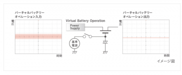
Let's settle on this thought, Nezbleu - all designs I use have either a proper shunt regulator, or are based on a pumped up cap multiplier as used in Technics top of the ine products. This is in fact a cap multilier with an added zener diode to fix the voltage and followed by a cap rated at not the usual 100 uF or so, but by one rated at 2,200 uF and ending with a 0.220 uF small value cap. Technics calls this a virtual battery and I adopted the name.
I got to this arrangement mostly by listening, i.e. trying out one and the other in turn to hear the difference, if any, and on occasion the difference was not good - back to the drawing board.
The other commercial problem is related to case and materials, exactly as John narrated it. The current cases are made of steel, while the fascial has an added all aluminium plate to satisfy the mod squad, which jusged audio quality by its the aluminium fascia thickness, but I admit I like it because of the low interference factor and the fact that this construction allows me to achieve a "3D" effect of knobs sort of coming out from behind the plate. Like the Kenwood amps of 1980.
Thank you; I enjoyed searching for Technics Virtual Battery on the web. This page from Technics' website seems to explain it best: link to jp.technics.com
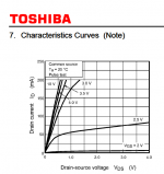
Aaaaaand, whoop de doo, it's a NMOS source follower. Some people call this a capacitance multiplier. Noise and ripple are present on the left hand terminal (the MOSFET "drain"). They are attenuated by a factor of (Zload * gds) where Zload is the impedance of the load (at the right hand terminal of the MOSFET, the "source") and gds is the output conductance of the MOSFET, i.e., the non-flatness of its I-V curve in the pentode region of operation). I've attached an I-V curve from a MOSFET datasheet which shows its characteristic non-flatness in the pentode region.
What they did not say, is that you can cascade several of these for better and better attenuation. In practice, in theory, and even in SPICE simulation.
_
Attachments
Last edited:
A recent LTC dual switcher will deliver +/- 15.6V at 200mA each, with 20mV pk-pk 1MHz sinewave-shaped ripple. Tack on a part of very low noise RF LDOs with 60+dB of ripple rejection at 1MHz from TI and you have yourself +/-15V at 200mA each with 20uV noise with no discernable ripple.
I really can't understand the hangup some people have with those huge ancient filth-spewing dirty-mains connected transformers; sooo 20th century 🙂
Jan
I really can't understand the hangup some people have with those huge ancient filth-spewing dirty-mains connected transformers; sooo 20th century 🙂
Jan
Yes, I am very 20th Century. I can't help it, as I spent the vast majority of my professional life there, BUT I am reasonably familiar with switching power supplies, as I first worked with one 50 years ago and of course since. RFI generators is what they are! It is easier for me to use a combination of linear IC regulators and passive cap multipliers, usually using complementary mosfets these days, than to insert a switching power supply.
Do you remember the part number, perhance Jan?
This guy might be pretty handy for me: http://cds.linear.com/docs/en/datasheet/3260fa.pdf
This guy might be pretty handy for me: http://cds.linear.com/docs/en/datasheet/3260fa.pdf
- Status
- Not open for further replies.
- Home
- Member Areas
- The Lounge
- John Curl's Blowtorch preamplifier part II