There must be a capacitor lurking in there that makes the open loop output impedance rise at low frequencies --- and yet it doesn't affect output current capabilities.
Its a R-R OPS, makes me wonder if this rising Zout at LF is a function of the biassing scheme. The datasheets are always very coy about those - presumably that's secret sauce - and show a block to indicate it.
I've been studying the 1642 et al. recently. Consider Fig. 30 on the datasheet. There must be a capacitor lurking in there that makes the open loop output impedance rise at low frequencies --- and yet it doesn't affect output current capabilities. Does look like a very nice part, the 5nV/sq rt Hz is good for JFET op amps, and of course very low current noise for most apps.
I worry about heavy loads transmitting thermal deltas to input stages, despite how exquisitely the layout has made the effects symmetrical. So for serious stuff I like to get the heavy lifting off chip, or at least to another chip. For real audio material this consideration is alleviated by the low duty cycle.
That's when composites become nice. 🙂
As far as datasheet vs Mr. Caldwell's comments, I'm going to to defer to the latter (given the other errors noted in the same said datasheet).
As far as datasheet vs Mr. Caldwell's comments, I'm going to to defer to the latter (given the other errors noted in the same said datasheet).
I concur, TI's DSs stopped being confidence-inspiring years ago.
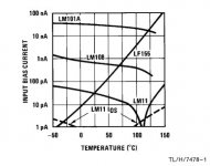
The other thing to worry a bit about is regardless of how low the bias current is at 25C ambients and quiescence, it doubles for about every 10 degrees increase. Still not likely a concern for reasonable external impedances, as would be used where possible to keep thermal noise down at or below the aforementioned 5nV/sq rt Hz, but just something to keep in mind. I remember in ye olde days when superbeta input bipolars were being compared favorably to JFET inputs at high temps.
The OPA1652's input offset current reaches a fairly staggering 1.6nA by 85oC. Presumably that's the leakage currents of the input protection diodes as the IPS is CMOS?
Added plot of leakage from Widlar's NS AN-241 on high impedance opamps.
Added plot of leakage from Widlar's NS AN-241 on high impedance opamps.
Attachments
Last edited:
No ........... But sweet into a pair of GalesYep, the High Voltage is very much part of the LM144's appeal - up to 80V total supply. LM344 is its commercial younger brother, not quite as high voltage though (68V). Did you run your amp bridged?
I wouldn't mess, usually, with CMOS front ends, although the low frequency noise has gotten amazingly better over the years.
I remember with MOS when the 1/f corner was around 10MHz.
I remember with MOS when the 1/f corner was around 10MHz.
He who waits, shall receive - it's true. I just had one of questions regarding op amps answere for me by Richard's remark related to hf behavior of op amps.
In my admittedly small experience, adding the output discrete current boost transistors usually made the biggest impact on the high range, rather than the bass lines, one might automatically assume for current boosting.
Some years ago, I was rying to use an OPA 275 op amp for a RIAA phono stage, along the lines as it was then used by some models of Harman/Kardon and Rotel. It worked well enough, but the treble just seemed to be dragging its feet somewhat. All right, but that's it, not as good as the midrange and bass. Fortunately, if anything I tend to overdo PSU bypassing, so I had ready and waiting additional bypass places and holes next to the usual 0.1uF next to the op amp, and I added encapsulated 10uF/25V tantalum caps in parallel with the 0.1 uF caps. This did clear up the treble range, nothing spectacular but the fact that I could hear it was reason enough. Now a part of this could be balmed on the quality of the PSU, which was a standard job using 7815/7915 regs, but that's how they are usually delivered anyway.
Just to check myself, I somehow managed to do the same on the H/K (no space on the Rotel), and indeed, I got a very similar result. I remembered then that I had once in fact seen this done in a project published in a German magazine, by one Holger Hermann, working for Burr-Brown in Germany, weho did the same and skipped the 0.1uF cap altogether, and relied on a tantalum 10uF/25V caps only. It wored well. Yet, everywhere else all I saw was the usual 0.1 uF cap, no doubt simplier and cheaper, but it seems insufficient method. Perhaps there's something in that?
Attachments

Any earnest suggestions on the 'optimum' IC general purpose, but great sounding IC?
LME49720HA , I became very convinced that it is a great sounding opamp when I "rolled" some into a phono stage and added heatsinks. The designer used lower noise units, but the LME49720HA (can type specifically) made the unit sound alive. It brought so much more everything at the cost of minor, minor, playback noise (for vinyl mind you). It really sounded like a dull plastic prior to the roll, but I didn't know till I tried it.
The maker now uses the non-can type in their new version; perhaps after me raving about the imrpovement.
Then I switched to a JFET based unit and haven't looked back! Ha!
I think I've chimed in on this subject in this thread before, so I'll be brief 🙂cheers:big cheers all around...):
I was the engineer who helped Richard in this challenge, and our contention was never there are not differences between amps, indeed there are often large measurable differences, but between different amps, with levels matched within 0.05dB, no clipping and any eq differences compensated for, there was not a "sound" to the amp which allowed a person to audibly differentiate it from another. ) just as is the case with throttle response in a car, if an amp has power, you will most likely use it.
<snip>
We discussed the Clark challenge some time ago, but back then we agreed that there might have exist some problems - at least with the documentation.
According to Clark´s notes several thousands tests were done and no individual got 65 % (or more) correct answers.
It is extremely unlikely (p(X=0 l 2000) = <e-6) even considering the best numbers in favor of Clark. The expected value (65% or more correct) is 151 by pure chance if only 2000 tests were done.
I've been studying the 1642 et al. recently. Consider Fig. 30 on the datasheet. There must be a capacitor lurking in there that makes the open loop output impedance rise at low frequencies --- and yet it doesn't affect output current capabilities. Does look like a very nice part, the 5nV/sq rt Hz is good for JFET op amps, and of course very low current noise for most apps.
I worry about heavy loads transmitting thermal deltas to input stages, despite how exquisitely the layout has made the effects symmetrical. So for serious stuff I like to get the heavy lifting off chip, or at least to another chip. For real audio material this consideration is alleviated by the low duty cycle.
I worked with the 1612 and it is a very nice part. The whole family has low distortion, which according to spec sheet is unfortunately fairly dependent on source resistance (unbalance?).
Yup, meta-not-blind. This will never go anywhere.
In the end results of controlled tests are necessary to confirm a hypothesis.
But you for yourself consider sighted tests as sufficient, provided that the result is negative, although you are quite often strongly biased against the audibility of an effect.
Obviously it is easy to not percept any difference as long as you know that the effect (not audible in you opinion) is under test.
Here's an illustration of how it is readily possible to design an audio circuit which accidentally relies on backwater parameters of an opamp, and where rolling therefore can have a tangible and audible effect. It is equally possible to design a circuit where it doesn't.
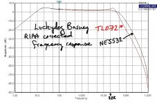
A few years back I designed a phono preamp based on an op-amp implementation of Barney Oliver's very nice discrete transimpedance diff-amp circuit. I overlooked GBW spec, as one might. However, the circuit is demanding of GBW, and it took ages to work out why the real circuit behaved differently from sims, and was very dependant on specific op-amp as to top end sound and f response.
Attached is an old plot showing difference between TL072 and NE5532 in that circuit, in terms of f response. This is entirely an artefact of the circuit: it would be readily possible for this not to happen at all, or to happen to an even greater extent depending just upon the circuit.
There's nothing wrong with NE5532/4 or TL072 in audio circuits (enough fine mixing desks are full of them), but it can be a matter of horses for courses as to circuit application, sometimes by complete design oversight.
Attachments
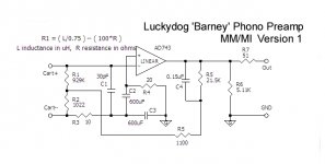
L and R are cartridge L and R?Here's a sketch of the schematic re my post above, I found it eventually. Note the pickup connection needs to have a floating ground.
No, it's one channel shown, and Cart + and Cart - are the cartridge coil connections, which float. L is cartridge coil inductance in uH, R is cartridge coil resistance in ohms. It's a floating MM/MI phono preamp with partial transimpedance loading, essentially forming the 75uS RIAA pole as a freeby.L and R are cartridge L and R?
I had to read the question twice before I spotted he meant the equation rather than left and right 🙂
US and UK english are different!
That's what he asked and you have confirmed.
But, I do Scots' english if you can understand the accent.
Should that be Scott's english since I was down at his wee hoose on Thursday. Abbotsford near Tweedbank on the part of the Waverly line that has been built after 40years of no trains.
That's what he asked and you have confirmed.
But, I do Scots' english if you can understand the accent.
Should that be Scott's english since I was down at his wee hoose on Thursday. Abbotsford near Tweedbank on the part of the Waverly line that has been built after 40years of no trains.
US and UK english are different!
Nothing to do with cross-pond linguistic differences. Just skimming the diagram and going 'what the hell is he on about'. Then spotting. If someone says 'Cartridge L and R' a fool in a rush can be forgiven for thinking its 'left and right' 🙂
😉I also write questions about crocodiles for certain exam boards😉 I misread bcarso's post to mean left and right too. Whatever, it means cartridge coil inductance (L) and coil resistance (R).I had to read the question twice before I spotted he meant the equation rather than left and right 🙂
Last edited:
- Status
- Not open for further replies.
- Home
- Member Areas
- The Lounge
- John Curl's Blowtorch preamplifier part II